


Hardware components | ||||||
_ztBMuBhMHo.jpg?auto=compress%2Cformat&w=48&h=48&fit=fill&bg=ffffff) |
| × | 1 | |||
 |
| × | 1 | |||
Software apps and online services | ||||||
 |
| |||||
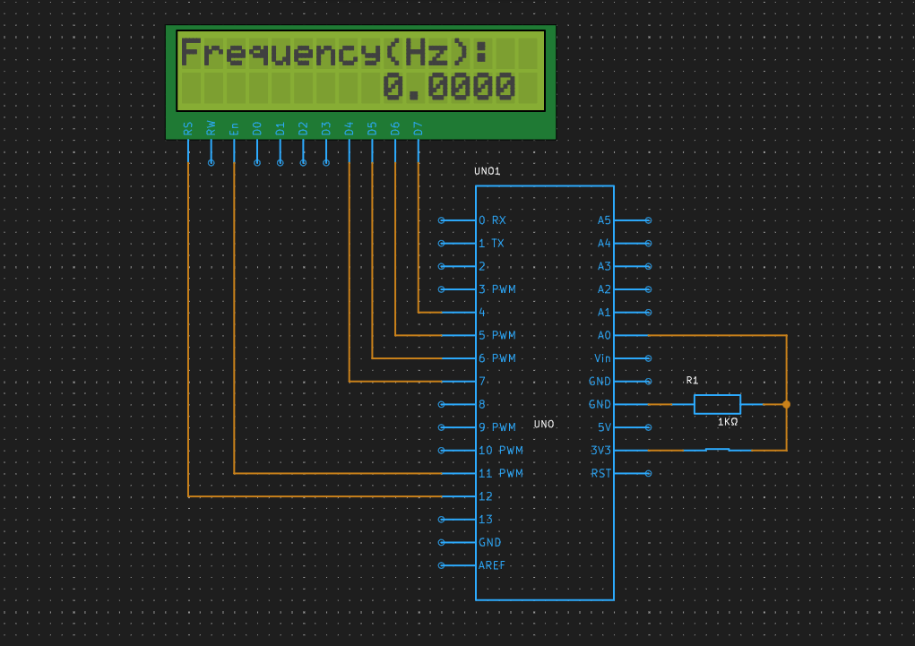
This project can measure the interval between switch presses to calculate the frequency and display it on the LCD screen.
This project simulates a frequency meter using an Arduino UNO board. The circuit includes an LCD display and a switch. The LCD display's RS, EN, D4, D5, D6, and D7 pins are connected to Arduino UNO digital pins 12, 11, 7, 6, 5, and 4, respectively. A switch is connected to analog pin A0 of the Arduino UNO.
When the switch detects a high signal, it triggers the Arduino UNO to start counting the pulses. The frequency is calculated by dividing 1000 by the average duration of the pulses. The result is displayed on the LCD, allowing users to read the frequency of the external signal source. This frequency meter can be used in various applications where pulse frequency measurement is required, such as in electronics testing, signal analysis, or educational demonstrations.
Simulate your at PCBX- https://www.pcbx.com/forum?mtm_campaign=E&mtm_kwd=hack


Comments
Please log in or sign up to comment.