We (most of us) really like Arduino because it's possible to make cheap clones, lots of libraries, examples, forum support and community out there.
Outside Arduino world, I like Cypress PSoC for some of its cool features like Graphical IDE, APIs, great features and understandable documentation.
I have bunch of PSoC® 4 CY8CKIT-049 4xxx Prototyping Kits.
The first half of this kit has CY7C65211 device, which is by default a programmable USB-UART serial bridge. I was thinking, maybe I can turn this part into a Arduino Porgrammer.
Bingo ! It worked, with a little bit of hack and a Uno Bootloader Atmega328P.
Arduino i.e. Atmegaxxx with Arduino Bootloader requires Rx, Tx data lines and DTR control line for uploading sketch.
Here is a pinmap of CY7C65211 chip -
We need following pins to be connected to Atmega328p for making a CyDuino -
But, unfortunately the DTR pin has no breakout to the edges.
Here is where I made a hardware hack. Scratch and remove the silkscreen and bring out a connection for DTR.
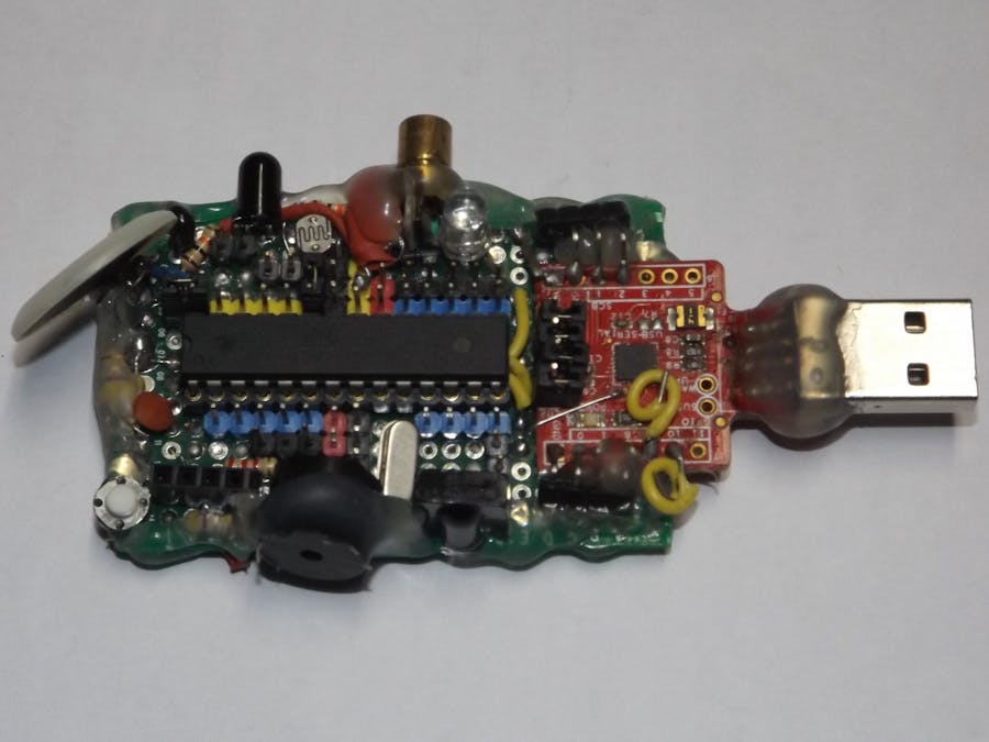
The GoodiesHere is an image of the finished project -
It's a ready to go board for Light, Sound, Temperature, Vibration, IR/Laser/Bluetooth Communication related projects.
Also, you can remove the jumpers from pin headers to disconnect on board sensors and connect to external components !
Features:- Programmable USB-Serial module
- Removable Microcontroller
- Touch+Push User Switches
- LDR Light Sensor
- Thermistor Temperature Sensor
- Peizo Vibration Sensor
- Laser Long Range Indication
- Bluetooth Connectivity (optional)
- IR Receiver
- RGB LED
- Buzzer
First, get a 4$ CY8CKIT-049 PSOC 4 Prototyping kit .
Next, we connect the Snapped part to PCs USB Port !
Also, Download and Install Cypress USBSerialSDKSetup
If everything goes well and drivers are installed for the chip, inside Windows device manager USB Serial Port will appear -
If driver not found for the chip, download driver from here
Now. Open Cypress USB-Serial Configuration Utility and click Select Target, then Connect
Click on SCB (Serial Comm Block)
Finally Program the USB-Serial Bridge
Now the thing is ready to build CyDuino !!
Step 2 : Building the CyDuino HardwareTo make it we need -
Bits and Pieces -
All I did is think, think, think and then solder the Components and Hot Glued the Bottom in a compact space. Sensors are placed near Analog I/Os, LED on PWM I/Os.
For IR Receiver, Buzzer, User Input Switches are connected to Digital I/Os.
There are 2 rails of Male header on both side, with the help of jumpers, any Sensor/On board devices can be connected/disconnected if needed.
The Atmega328P MCU is placed on IC socket for ease of removal, so the thing is production ready - you can burn same program on multiple MCUs for making multiple projects.
The DTR connection is hacked like this -
Step 3 : Testing the CyDuino in Arduino IDE
I am using Arduino IDE 1.0.6 here. Once, the board is developed - it's time to test it!
First we need to select the COM port (here COM 3).
Next, according to the hardware connections we can program for any project possible with it.
-
There you have it! A nice, sensor loaded Arduino Dev board with lots of goodies!


Comments
Please log in or sign up to comment.