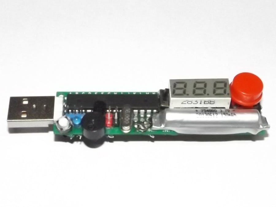
This is a story about making an pocket carry-able USB stick like IR Thermometer made using Arduino programming and some other stuff. The device will also have stopwatch function, kitchen timer and inactivity tracker function.
IR Thermometer is an IR radiation-based temperature sensing device which allows for the measurement of the average temperature of a surface it's facing - most probably with Wien's displacement law or Stefan–Boltzmann law from highs school physics.
A stopwatch is a basic time measurement device used in sports, scientific experiment, etc. to measure lapsed time. Today, hardware stopwatches (the analog type) are kind of extinct and replaced by a so-called smartphone app. A kitchen timer is a device that alerts cook by buzzing an alarm set such that something being cooked needs checking.
An inactivity tracker is a periodic timer that alerts a person to move after every X amount of time. This helps one to get a minute break from idle state and practice healthy life.
Hardware DescriptionThe finished device looks like this:
Here is a nice description picture of the thing:
Step 1: Gather all the ingredients, imagine and make a mental map of what goes where!
Take measurements, make necessary holes, place components and solder.
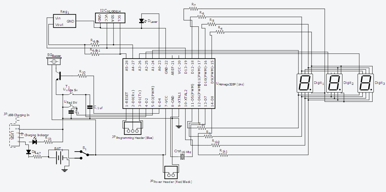
Step 2: Use heat shrink tube and 0 Ohm resistors to interconnect things, 1k resistors on display segment pins, and solder according to the schematic.
Step 3: Interconnect both layers.
Step 4: Upload test code and check if everything operates. If so, align top and bottom layer with toothpicks and warp on both ends with thin tape.
Now, fill the gap with the hot glue and wait 5 minutes. Now, your sturdy device is ready to roll.
Here, we will use our good old friend, Arduino IDE, to write the program.
Before we get into code, let's get an idea how the hardware connections affect the code. The small white momentary push button is the menu selector switch which is interrupt driven; the same goes for the big red push button - connected for falling edge INT 0 and INT 1 on Digital Pin 2 and 3.
Digital pin 4 is the buzzer driver pin and A0 is the laser driver pin. A1, A2, A3 are display digit pins; pins 5-12 are segment pins. A4, A5 Digital Pins are for I2C communication with the IR sensor.
Finally, thanks to Dean Reading for the Arduino 7-Segment Library and Limor Fridge for the Arduino MXL90614 Library - life made easy! Based on their library example, the basic code is developed - right now only Ambient and Object Temperature detection function is enables.
I will add the other functions soon! So, stay tuned.
Action!Here are some temperature measurement results photo and a video - enjoy!
- The IR Sensor has 90 degree field of view, which means it is not measuring the temperature of the point where the laser pointer is shining, rather it is averaging the temperature of objects on its view plane.
- The system runs with 4.2 volt fully charged Li-Po battery and should operate with at least 3.7 volts without worries.
- Laser is directly driven from MCU pin and buzzer is driven through transistor.
- One of the digital pin powers the 3.3V regulator and the IR sensor.
- 11 pins are required to direct drive the 7 segment display.
- The device is rechargeable from the USB port of PC/Laptop. From the USB, 5 volts are reduced to 4.2 with a diode and a resistor in series - simple charging circuit where the blue LED glows while charging.
- The program can be updated through the 3 blue male header pins (Reset,RX,TX) connected through the external USB-FTDI (serial) device, which is detected as Adruino in Arduino IDE.


_ztBMuBhMHo.jpg?auto=compress%2Cformat&w=48&h=48&fit=fill&bg=ffffff)


_3u05Tpwasz.png?auto=compress%2Cformat&w=40&h=40&fit=fillmax&bg=fff&dpr=2)
Comments
Please log in or sign up to comment.