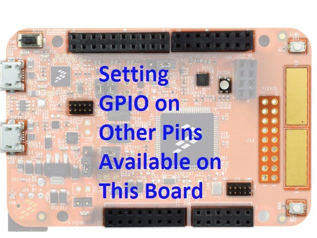
This short tutorial is about setting Output on other pins rather than the on-board RGB I/O pins !
I am currently trying to figure out the Ins & Outs of this Kinetis Freedom K82 kit for my submission for the "Flexio : Flex Your Mind" challenge .
After struggling for a while, I managed to set Output on other unused pins of the board.
Resources for Getting StartedFirst follow exactly all 4 steps from the link below and setup KDS environment on your PC
Getting Started Videos Freedom K82 Videos
Once you are through step 4, see if you can set Output on PortB Pin 16 (PTB 16).
If you can't follow next steps then keep reading .....
Important !If you have watched the getting started videos, from the 4th video you should know how to create new project using c program for the freedom k82 board. Create a new project according to the instructions of that video.
Now, we will set PTB16 as Output by following these steps :
Open Pin_Mux.c
Inside BOARD_InitPins() function
Step 1: Enable- Port Clock which will allow the I/O port to be configured
CLOCK_EnableClock(kCLOCK_PortB); // enables PortB Clocking from SIM moduleStep 2: Set Port Name, Port's Pin Number, Mux (to select pins as GPIO/I2C/UART/Analog/ect)
PORT_SetPinMux(PORTB, 16U, kPORT_MuxAsGpio);
// Sets PTB16 ie Port B Pin 16 as GPIO pin
In Main C
Step 3: Set the Pin As Input/Output with config Struct
gpio_pin_config_t pin_config ={kGPIO_DigitalOutput,1, */ pin_config struct hold pin configuration for Output pin 1 for output and 0 for input /*};and call BOARD_InitPins() from pin_mux
// this function from pin_mux.c executes step 1,2BOARD_InitPins(); BOARD_BootClockRUN();BOARD_InitDebugConsole();Step 4: Use Config Struct to Initialize the Pin
// Initialize PTB16 as OutoutGPIO_PinInit(GPIOB, 16U, &pin_config); Step 5: Call APIs to write or toggle Output
GPIO_WritePinOutput (GPIOB, 16U, High);// writes 1 on PTB16GPIO_WritePinOutput (GPIOB, 16U, Low); // writes 0 on PTB16Following are the steps to make 3 channel PWM ( to make RGB color mix).
Create a new project with KSDS_Project_Generator.exe and paset the Code from PWM Main.c to the new project's main.c. Then paste code from pin mux of PWM to pin_mux.c of new project, compile, flash and go !
Code for step 1 & 2 are written in Pin_Mux.c file
and executed on step 7 in main.c file
===================================================
K82 Sub-Family Reference Manual pages 215-222
provides these info
===================================================
Base : FTM0/FTM2/FTM2/FTM3 >>> indicated FTM module (only Availabel on Device will work)
Channel : 4U/5U/6U  (Channels of a Module wired with Hardware Pins)
PinMux : kPORT_MuxAlt3/4/5 ( Mux option of Pins of a Port )
Pin Name : PTC8/9/10 ( Port Pins )
===================================================
For example from page 218, K82 LQFP 100 pin MCU's 42th Pin has:
===================================================
Pin Name : PTA12 which means -  PORTA, 12U
Base : FTM1
Channel : 0U
Pinmux for FTM: kPORT_MuxAlt3
===================================================
===================================================
===================================================
Steps to generate PWM :
===================================================
STEP 1: Configure Port Clock for Pins Accociated with FTMn
KSDK API Ref Manual 2.0 page : 38
===================================================
Step 2: Configure appropriate Pin Mux for FTMn
K82 Sub-Family Reference Manual page 215-222
===================================================
Step 3: Include Header Files
===================================================
Step 4: Get Source Clock and Define as FTM (PWM) Clock
KSDK API Ref Manual 2.0 page : 40
===================================================
Step 5: Declear a FTM Configuration Type Variable
KSDK API Ref Manual 2.0 page : 506
===================================================
Step 6: Set PWM Parameter: Channel_pin_number, level, duty, edge
KSDK API Ref Manual 2.0 page : 506
K82 Sub-Family Reference Manual page 221
===================================================
Step 7: Initialize Port Clcok, Mux (Step 1,2)
===================================================
Step 8: Load default FTM Config on FTM Configuration type variable
KSDK API Ref Manual 2.0 page : 514
===================================================
Step 9: Initialize FTMn Module with the loaded config variable
KSDK API Ref Manual 2.0 page : 513
===================================================
Step 10: Setup FTM_PWM : FTMn, PMW_Parameter (Step 6), Number_of_PWM_Channels, PWM_Wave_type, Wave_Frequency, FTM_Clock (Step 4)
KSDK API Ref Manual 2.0 page : 514
===================================================
Step 11: Starting FTM Module (& Stopping if needed)
KSDK API Ref Manual 2.0 page : 519
===================================================
Step 12: Updating Duty_Cycle and  FTM_Config Register wit Software Trigger
KSDK API Ref Manual 2.0 page : 515
KSDK API Ref Manual 2.0 page : 522
===================================================
Similarly to set a pair of pin as I2C -
*/ this function is defined in pin_mux.c , it initializes the I/O as required for the project /*
void BOARD_InitPins(void)
{
*/ declaring a port_pin_config_t type structure To hold pin initialization settings, Yes, port_pin_config_t is a type like int,float,char And pinConfig_t is like the variable x,y,z*/
port_pin_config_t pinConfig = {0};
*/ create config setting as pull up and open drain as per I2C hardware requirement */
pinConfig.pullSelect = kPORT_PullUp;
pinConfig.openDrainEnable = kPORT_OpenDrainEnable;
/* Activate the port clock */
CLOCK_EnableClock(kCLOCK_PortB);
/* Load above pinConfig setting on PortB-Pin 0,1’s Configuration Registers */
PORT_SetPinConfig(PORTB, 0U, &pinConfig);
PORT_SetPinConfig(PORTB, 1U, &pinConfig);
/* I2C0 PIN_MUX Configured as I2C pins */
PORT_SetPinMux(PORTB, 0U, kPORT_MuxAlt2);
PORT_SetPinMux(PORTB, 1U, kPORT_MuxAlt2);
/* from K82 ref manual page 219 Alt2 pin mux setting connects Certain pins to I2C peripherals, */
}
This I2C code only makes a pair of Pin I2C, but using it in the main code is your homework !
See Chapter 24, Page 525-530 for I/O config APIsc
More ResourcesStart with this Freedom K82 Board manual to know which pins are connected to RGB LED, Switches, Accelerometer, Jumpers and Power Options !
To know about Electrical Characteristics (voltage, current, power, frequency etc) of the MCU check this
Boring Webinars (but don't skip these) :
Sweet voice Trainer explaining Peripheral Hardware, Blocks Interconnections and Software Configurations (must listen) :-
A better way to learn is to watch Kinetis K Series MCU Online Training
What are these ? Where do I find them ?PORT_SetPinMux(PORTB, 0U, kPORT_MuxAlt2);CLOCK_EnableClock(kCLOCK_PortB);CLOCK_EnableClock(kCLOCK_PortB);These are APIs(functions) to do things, so you don't need to dig into Register Level of ARM. Check this API guide to understand how to write codes :
See Chapter 24, Page 525-530 for I/O config APIsc
See Chapter 12, Page 213-222 for Mux/Alternate Pin Signals


Comments