

Hardware components | ||||||
 |
| × | 1 | |||
_ztBMuBhMHo.jpg?auto=compress%2Cformat&w=48&h=48&fit=fill&bg=ffffff) |
| × | 1 | |||
 |
| × | 1 | |||
 |
| × | 1 | |||
| × | 1 | ||||
| × | 1 | ||||
 |
| × | 1 | |||
 |
| × | 1 | |||
 |
| × | 1 | |||
 |
| × | 1 | |||
 |
| × | 1 | |||
 |
| × | 1 | |||
 |
| × | 1 | |||
 |
| × | 1 | |||
Software apps and online services | ||||||
 |
| |||||
Hand tools and fabrication machines | ||||||
 |
| |||||
It happened to me few times, when I was in the bathroom/toilet and water ran out in the middle of doing something !
That's why I have decided to make this wireless water level sensing system which can monitor water level in the rooftop water tank (6th floor) and sent the information to (1st floor) wirelessly. The remote water level sensing transmitter is solar powered for self-sustaining operation.
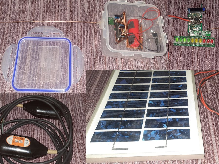
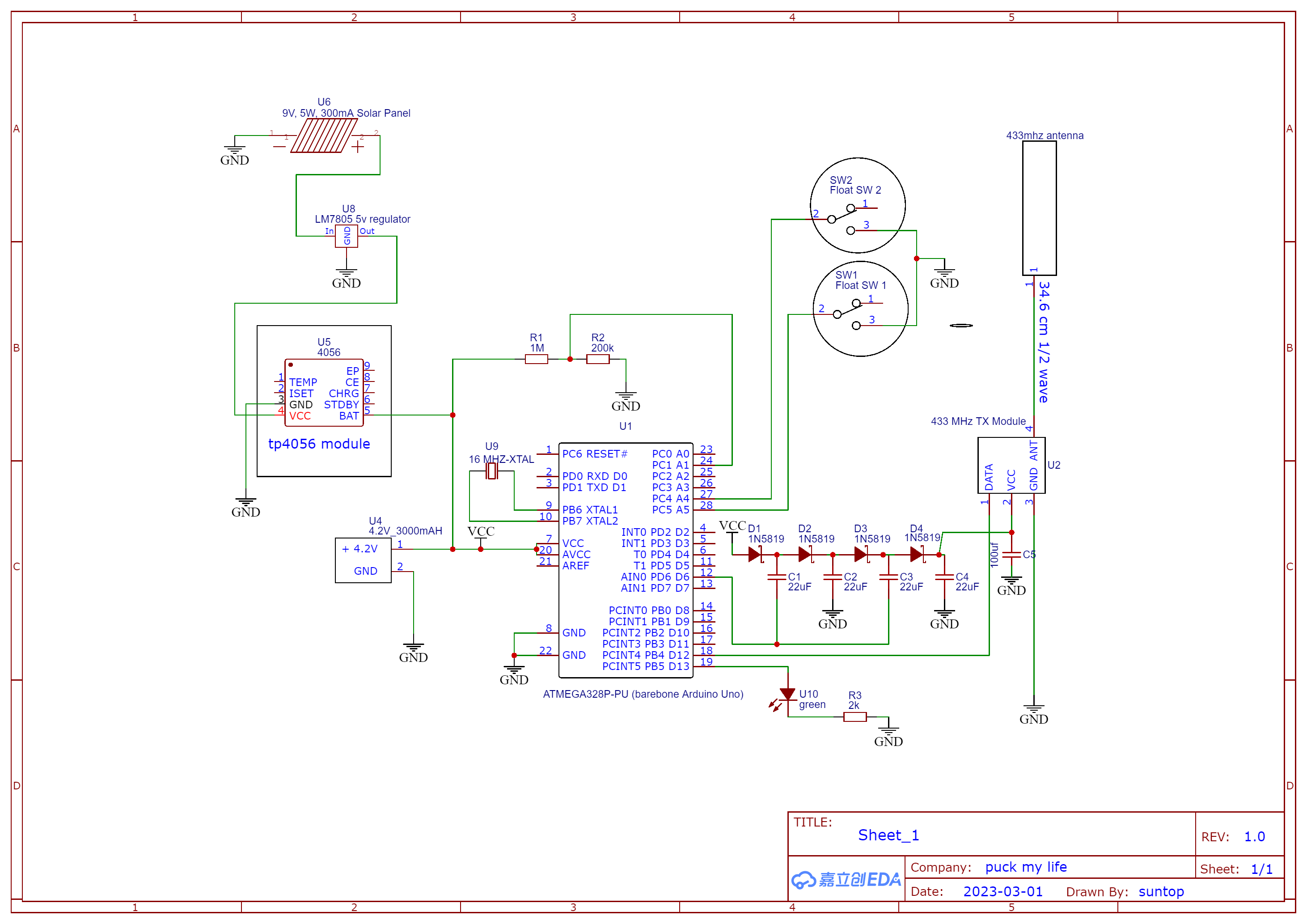
Hardware BuildThe Transmitter: The transmitter setup consists of
- 433Mhz transmitter module,
- 34.6 cm long 1/2 wave antenna,
- bare bone ATmega328P running as Arduino Uno,
- 3000 mAh refurbished lipo battery,
- TP4056 battery charging circuit,
- LM7805 voltage regulator
everything inside a plastic enclosure.
Solar & Battery Charging: To generate power and recharge the battery, there is a 5W (9V, 550mAh peak) solar panel.
Water level Sensing: To sense the water level, I am using only 2 float switches, because I only care about nearly full, nearly empty and in-between water levels.
N number of float sensor/switches can give N+1 number of level detection but it will cost more money (the thing that I almost never have enough).
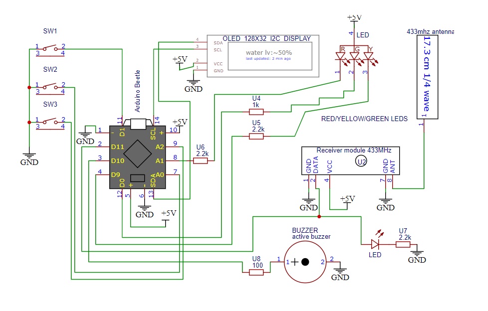
The Receiver: The receiver setup consists of
- 433 Mhz receiver module,
- 17.3 cm 1/4 wave antenna,
- Beetle board (Arduino Leonardo on ATmega32u),
- 1306 OLED Display,
- water level indication Red/Green/Yellow LEDs,
- 5v power power adapter
Wireless Communication:433 MHz frequency provides longer range and less crowded spectrum (compared to BLE/WiFi). Your WiFi range is horrible ? That's because there are too many networks !
Self-Sustaining Power: 3000 mAh oversized LiPo battery, recharged with oversized 5W panel for week long operation, ensuring the system is functional under bad weather condition.
Long Autonomous Operation: Low Power Sleep mode operation by Arduino Sleep to save power, periodically sends water level data and battery voltage info about every 3 minutes, each data is sent 4 times to ensure at least one uncorrupted data packet is received. By using of Radio Head library in the code, packets are sent with preambles, start/stop bit, proper encoding to ensure wireless data integrity.
OutdoorOperation:Waterproof, air-tight enclosure for weather proof operation.
Antenna: By pulling out "just a piece of copper wire strand" from any of power cable and sizing it to match 1/2 wave antenna (34.6 cm) for the transmitter and 1/4 wave antenna on the receiver (17.3 cm). I have tried 1/4 and 5/8 wavelength antenna on transmitter but 1/2 wave seems more reliable.
Range: The distance between transmitter and receiver is about 15m and there are few concrete floors and brick walls in between.
Device Operation: Hardware & Code explainedThere are few quirks going on with the hardware. Let's explain them:
Reliable 433 MHz communication : 4 things can make 433 MHz communication reliable
- Higher supply voltage thus larger amplitude d
ata pulse modulation - Slower bit rate data transf
er or wider data pulses - Proper antenna type/size and polarization/orientation
- Receiver sensitivity/noise immunity or bui
ld quality of the modules
The 433 MHz transmitter and receiver use simple ASK (amplitude shift keying), 1's and 0's are modulated with 433 MHz carrier signal with changing amplitude. The transmitter module can operate anywhere between 3-12V. Using a higher voltage (i.e. 12V) for the transmitter will make the amplitude bigger, yielding longer range or deeper penetration of signal through obstacles.
Sending data at a slower bit-rate (I have choose 128 bit/s) makes the 1's and 0's wider in the career wave, this also helps to achieve longer range, less corrupted/more reliable data transfer. This can be done from the arduino code
Next important thing is using appropriate antenna length, as RF emission pattern depends on antenna type and size. For 433 MHz, 1/4 wave antenna is widely use because it is smaller. I recommend using straight monopole 1/2 wave antenna for 433Mhz Project, avoid using coiled up or pcb trace antenna. If size is not an issue, 1/2 wave antenna is better than 1/4 wave antenna. For extra range 5/8 wave antenna can be used but their radiation pattern makes them difficult to align in the correct polarization.
- 1/4 wave 433 MHz antenna = 17.3 cm long single core wire
- 1/2 wave 433 MHz antenna = 34.6 cm long single core wire
- Both transmitter and receiver antenna must be oriented similarly on the same plane meaning they both must have vertical polarization or both must have horizontal polarization.
- For horizontal plane range both antenna must be vertical to earth
- For vertical plane range both antenna mustbe horizontal to earth
Since, I am sending data from roof (6th floor) to 1st floor, both my transmitter and receiver antenna are in Horizontal Polarization
Lastly, performance varies from module to module, receiver with higher sensitivity will be able to capture the data packets better. The RXB6 model (this one is shielded and uses 433 MHz crystal) receiver is better than the FS1000A model (this one uses Inductor based LC oscillator).
Dickson Charge-Pump Voltage Booster: The remote unit (transmitter setup) is powered by 4.2 volts LiPo battery but the transmitter module itself can take maximum 12 volts. Powering the module with maximum voltage gives stronger RF output, thus longer and reliable data transmission.
So, how to get 12v cheaply and easily from 4.2v battery ? Charge-Pump ! Just few diodes and capacitors in voltage multiplier configuration, driven by one of the PWM pins of arduino, I can easily get 12v.
The diodes need to be low dropout Schottky diode 1N5819, the capacitors are 10uF/22uF multilayer ceramic type, the last stage needs a bigger capacitor somewhere between 100-470uF.
AVR Sleep, Watchdog Bark, Power Consumption: Solar powered hardware must conserve power for bad weather. Although the 3000mAh battery is oversized, I have programmed the ATmega328p on the transmitter setup to sleep about every 3 minutes before sending updated water level data. During sleep, it only consumes 130 uA current, which can increase another 120-250 uA if the float sensors pull-down the pull up resistors. The Watchdog timers wakes up the mcu every 8 seconds to keep track of time, during this short window current consumption is about 10-11 mA for few milliseconds. About every 3 minutes the PWM turns on the Charge-Pump to power the transmitter module, current consumption is 25-27 mA for 7-8 seconds during wireless activity.
Float Sensor and Counter Weight: Float sensor is basically a mechanical switch inside a floating enclosure that opens/closes based on its orientation. With the rise and fall of water level as the float sensor position changes, there is a conductive ball inside it which rolls from one side to the other side to activate and deactivate the switch. To avoid oscillation, there are grooved chambers which keeps the ball in place until the water level crosses a certain point, which basically acts like mechanical hysteresis. To keep the float sensors from floating all the way top, when the tank is full, there are counter weights which keeps them where they are suppose to be.
Things Happening on Receiver side: The receiver setup is always listening for meaningful data. Radio Head library related code takes care of the incoming packets. Then some software filtering is done to extract the transmitter battery voltage information data and water level data. This is done by checking the first character of a data packet. The battery voltage data will be sent from the transmitter with 'B' as the leading character, followed by the ADC value.
(see code below for details)
1306 OLED Display is driven by U8GLib library, this display will show approximate water level and how much time has passed since last packet received. If something breaks on transmitter side or transmission gets corrupted, the time passed info will be more than 3 minutes.
The Red/Green/Yellow LEDs is a quick way to check the water level from a distance. Green means the water level is somewhere between 50% and nearly full, Yellow means the water level is somewhere between 50% and above 20%, Red means water level is almost empty or less than 20%.
Here is my setupIf you need any additional info regarding this project, ask your queries in the comment section. I will try to answer
ReferencesHow 433 MHz modules work with Arduino
How to put Arduino into Sleep and Save Power
How to use Charge Pump Voltage Multiplier with Microcontroller


_3u05Tpwasz.png?auto=compress%2Cformat&w=40&h=40&fit=fillmax&bg=fff&dpr=2)
Comments