


Hardware components | ||||||
 |
| × | 1 | |||
 |
| × | 1 | |||
 |
| × | 1 | |||
 |
| × | 1 | |||
 |
| × | 1 | |||
Software apps and online services | ||||||
 |
| |||||
Build an instrument that measures the speed with which a wheel spins.
A magnet is attached to a wheel and a magnetometer located in close proximity detects when the wheel revolves. Each revolution is timed and RPM is inferred.
Why I use XinaBox xChipsXinaBox components ('xChips') use a connectivity standard that doesn't require wires, soldering, breadboards or any hardware knowledge at all. I have absolutely no skills or confidence when it comes to circuit building, but that is no barrier now to what I can make.
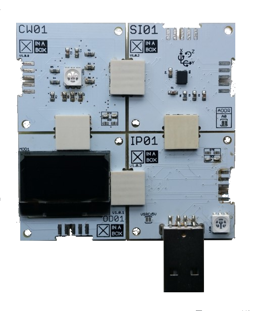
For this project you will need the following xChips:
- The xChip CW01 (ESP82666 Core) is a Wi-Fi module as well as a core. Here we use it just as a core - we will flash code from the ArduinoIDE on to it.
- The xChip SI01 comprises of 3 sensors: a 3-axis accelerometer, a magnetometer that computes orientation to magnetic north and measures magnetic field strength in 3 axes and a gyroscope that measures orientation to the center of the earth. For this project we just use the magnetometer.
- The xChip OD01 is equipped with an OLED display unit, 64x128, that is capable of displaying graphics or text. We use it here to show the number of rotations and the RPM calculated over every 10 rotations.
- The IP01 or IP02 xChip is a USB programming interface that we use to flash code onto the CW01 core. It can also be used to power the circuit. An alternative way to power the circuit is to use the PB01 xChip, which carries a dual AA battery pack.
The magnetometer (SI01) is attached to a fixed position relative to a spinning wheel (which has a small, strong magnet attached). When the wheel spins the SI01 xChip detects changes in the magnetic field: readings are high when the magnet is close and low when it is further away. We look out for the transition from high to low and record these events as a rotation. The OLED display (the OD01 xChip) is used to output related measures - here we count the number of rotations and infer the RPM.
Step-by-Step- Hardware Setup
- Installing Arduino Libraries
- Code
- Applications and Results
- Summary
- Connect the xChipsCW01, SI01, OD01 and IP01 together using the xBus connectors. You may connect it as shown in the diagram below.
- Then connect the IP01 to your PC / laptop USB port. This provides power to the circuit, but more importantly it allows us to flash code from the PC / laptop to the CW01 core.
Please see this guide on how to assemble xChips.
Installing Arduino LibrariesInstall these Arduino cores/libraries:
1. ESP8266 Core
If you are unsure of the process of adding libraries or cores / boards to the ArduinoIDE, please refer to these guides on installing libraries and cores.
NB: Once you have installed everything as above, in the ArduinoIDE select XinaBox CW01 from the available list of boards.
CodeUse the code attached to this project - paste it into ArduinoIDE, compile then upload to the CW01 (which is attached to your coding device by the IP01 via UART).
Ensure you have selected XinaBox CW01 from the available list of boards. If you cannot see it as an option go back to the previous section and ensure everything has been installed correctly.
The code has the following flow:
- Initially some calibration is done. When you power up the instrument it spends several seconds reading the magnetometer, and you should spin the wheel during this period. It will store the maximum reading it detects - this value will correspond to the closest point of the magnet to the magnetometer.
- Once the calibration is complete the program uses a switch to mark where the wheel is relative to the magnet:
- Switch = HIGH: When the magnetometer reading approaches the maximum value (by exceeding a threshold set by us in the code) it means the wheel magnet is close to the magnetometer. Our switch is set HIGH
- Switch = LOW: When the reading then declines it means it has moved further away. Our switch is set LOW.
- When we observe the switch change from HIGH to LOW we infer that the wheel has rotated and we record the time between spins.
In tests I was able to poll the SI01 just over 100 times per second, so I reckon 10ms between readings is feasible. This is important - there is an upper limit on the number of rotations that we can measure, as this image will help show:
To detect a valid revolution of the wheel the magnet has to pass through 2 zones (HIGH, which is the blue zone, and LOW, which is the rest). This means that the method cannot work for speeds greater than 50 revolutions per second - the 'resolution' is just too low. But the actual limit is much more stringent than that:
To detect a valid revolution of the wheel the magnet has to pass through the blue zone AND be recorded by the magnetometer whilst INSIDE the zone. The size of this blue zone is determined by the strength of the magnet and the proximity of the SI01 to the magnet. In the image above the blue zone occupies 1-sixth of the circumference, so if we can read the magnetometer 7 times per revolution we should be able to confidently detect a full turn. At 100 readings per second this puts the upper limit of accuracy for the image above at about 13-15 revolutions per second.
In the following section I will show you the calibration device which I used, and which you could use to infer the upper limit of rotations per second that your instrument can measure.
Troubleshooting Note: if the code compiles fine but you have trouble uploading it to your device try connecting JUST the CW01 and the IP01 together then plug that in to the USB on your laptop. I have found that on occasions when ArduinoIDE struggles to upload the code, this often sorts it out.Applications and Results
There are many applications for this technique, including the 3 shown below:
1:The test rig / calibration tool:
During the build process I used a wheel I made out of cardboard and some light scrap wood, with a handle in the middle so that I could rotate it. This was for testing and calibration, so its not pretty! I had some strong little magnets on my fridge that I used, and I am sure their strength helped a lot.
A test rig like this one will be useful to you as a calibration tool, if you are thinking about implementing this in a real world context. Use it to assess the distance that the SI01 magnetometer will need to be fixed from the path of your magnet, and get a sense of the size of your 'blue zone'. Use this to infer the maximum revolutions per second that your rig can support.
FYI I had a couple of inches to play with - not much but enough. I estimate about 1/8 to 1/tenth of the circumference was in the blue zone. but there is no way I could spin that at 10 revolutions per second to test it properly!:
Note on the image above: for power I used the PB01 xChip with 2 AA batteries instead of the IP01, but either is fine. If you look closely you will also see I’ve used an MD01 xChip on the bottom right of the circuit. This is a blank which I could omit but I include to give more strength to the circuit. It also adds redundancy.
2: A measuring wheel.
A measuring wheel is used to measure distances. Traditionally the circumference of the wheel was a known distance (say, 1 yard), so all you had to do was count the number of rotations and you knew the length of something (a sports field, the length of pipe needed, how much road to build). Here the SI01 keeps count of the rotations for us and the code we used can be adapted to show the distance.
3: A bicycle speedometer.
The kit is perfectly suited to bling up your bicycle.
In the picture below I’ve used two AI04 xChip extenders and 'standard' RJ11 cable (MUST be 4 wire or 6 and twisted) to separate the circuit. This allows me to place the SI01 near the wheel and the OD01 on the handle bars:
I used cable ties and string to fix everything to the bike. A neat 3d printed case for the handlebars (with side-bars to block the sun) would work very nicely and a very stable housing for the SI01 is a must (it needs to be close to the wheel). I didn't send my lad out on the road with this dodgy setup, by the way: I didn't trust my cabling enough.
It's just a POC, for now, but the authors have plans for more in this vein - other features of the SI01 (magnetometer and gyroscope) can be utilised to enhance bicycle telemetry.
SummaryIn this project we have used XinaBox kit to build an instrument that uses a magnetometer to measure the number of times a wheel spins. Combining the number of spins with the time taken for a spin and the circumference of the wheel allows us to measure things such as speed, distance and RPM.
The project has a number of useful applications, e.g. build a measuring wheel or bling up a bicycle (or similar wheeled vehicle). If you come up with any other useful applications please let us know :)
Building the XinaBox RPM circuit


Comments
Please log in or sign up to comment.