- IR receiver
- 5V relay
- CD4017 IC
- IN4007 diode
- 100K & 1K resistor
- BC547B transistor
- 104pF Ceramic capacitor
- Old 5V mobile charger
- Connector
- TakeCD4017 IC. And connect pin 4 and 15, pin 8 and 13 using a cable for each as in the 3rd photo.
- Bend the pins 3, 4, 8, 13, 14, 15, 16 to side ways and cut the remaining pins.
- Connect a 100 k resistor on pin 14 and 16.
- Connect a 104pF capacitor between pins 13 and 14.
- Take the BC547B transistor.Attach Emitter to pin 8, Base to pin 3 with a 1k resistor in between, Collector.
- Take the IR receiver and connect wires green to pin 1, yellow to pin 2, orange to pin 3 of the senor.
- Then connect the green wire to pin 14, Yellow wire to pin 13, Orange wire to pin 16 of the IC.
- To the input side of 5V Relay connect the IN4007 diode.Place the negative side of diode to pin 1 of relay and other side to pin 3 of relay.
- Now connect the collector pin of transistor to pin 3 of relay.
- Connect pin 1 of relay and pin 18 of IC using a wire.
- For power supply we are using a old mobile charger with 5V output.
- Take the charger module out from the case.
- Connect a wire to input side and out side of charging module.The using a insulation tape insulate the charging module.
- Attach the Positive output to pin1 of Relay and Negative output to Pin8 of IC.
- Then add a connector on both side. Connect the negative and positive wire of charging module to input connector.
- Also connect the Neutral of both the connector together using a wire(Black wire).
- Give Line voltage to Relay using a wire connecting Line and Relay pin 2(Common-Brown Wire).
- Then connect the NO-output pin of relay to Output Line Voltage side of connector.
NB:USE HIGH GAUGE WIRE WHILE CONNECTING THE LINE AND NEUTRAL DIRECT FROM SUPPLY.
Step 6:TO make a case I used LED bulb cap and bottle cap.
- Take both the caps
- Add 1 hole on the top of LED bulb cap for IR receiver.
- Add hole for INPUT and OUTPUT for supply wire in bottle cap
- Insert and attach the entire circuit on the caps and Glue it together.
- Give a small marking on INPUT side and OUTPUT side for identification of terminals.
- Insert a Bulb on OUTPUT terminal and connect the INPUT to supply
- Check the working using a IR remote.
- Cut the wire between supply wire and fan
- Connect the device we build in between it.
- Now switch on the supply and test it using the remote
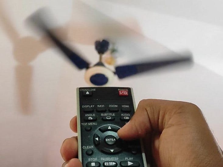
We can control this fan using any IR based remote.
We can also control it using a phone that have IR sensor.(For example in MI phones which support MI Remote APP)
Step 10:Here I used mostly components without a proper circuit board.You can build it in much better and efficient way using a PCB. Therefore, in case you want your own PCB, you can obtain through this link on PCBWay.com. You can also order good quality PCBS from PCBWay.com at low cost. In addition to the standard pcbs, we could also support advanced Pcbs, FPC/rigid -flex Pcbs, rapid-rpototyping and other related services that could meet your needs to the most extent.
PCB order steps on PCBWay:
- Visit the website: www.pcbway.com
- Click PCB Instant QuoteClick
- quick-order PCB Upload the gerber file by clicking "+Add Gerber File" and wait until the gerber file is finished
- uploading Set the PCB specifications as you wish, starting from the number of PCBs, the number of layers, thickness, color and others.
- After that, look at the left, it will display the estimated cost
- processing time and delivery service selected
- Click Save to cart


Comments
Please log in or sign up to comment.