


Hardware components | ||||||
 |
| × | 1 | |||
Software apps and online services | ||||||
 |
| |||||
| ||||||
Hand tools and fabrication machines | ||||||
 |
| |||||
 |
| |||||
 |
| |||||
Old and faulty embedded devices are my favorite choice for couple of reasons :
- Perfect target for Hacking/Reverse Engineering practicing.
- Helps understand more about the Embedded Systems.
- Definitely evokes Nostalgia.
- Enhances Repairing skill, which indirectly can help reduce e-waste. Furthermore, succeeding in getting the broken things back to life is an experience like none other.
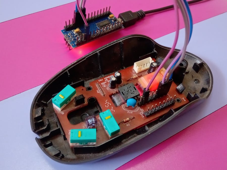
I had an old optical mouse (> 10 years old) lying around, which also had it's USB cable missing. Having watched a video (link at the end) about how mouse works, I decided to give it a try before discarding it as trash. Mainly, I was interested in reading displacement data of mouse using an Arduino or any other microcontroller.
Hence, I opened the mouse (photos above) and some things became immediately evident :
- Single sided PCB, very easy to trace even with naked eyes.
- Only two IC (Integrated Circuit) on the PCB, definitely one at the center is optical sensor and other one is controller. Also both are Through Hole type.
Step 1 : Identify the ICs
- The controller IC had part number : Logitech 361335-A000, I was not able to find any related document available on internet for this one.
- The optical sensor had part number : A2610, and its detailed documentation is available on internet, although this part ADNS-2610 has been now marked Obsolete on Digikey (Link at the end).
Step 2 : Prepare Development Hardware
Having not found any information about main controller IC, the best chance I had was with the optical sensor only. There are two ways to proceed further based on whatever information was available in datasheet of the optical sensor :
- Desolder the optical sensor from PCB and create a new temporary sensor board. Since the sensor requires external clock of 24kHz and also LED and lens focusing assembly, this option will result in lot of effort.
- Desolder the controller IC and instead solder header in its place. Connect these header pins to arduino using jumper cables. This option is relatively straight forward as all the supporting circuitry (clock, power supply, etc.) for optical sensor is still there on PCB and also the mechanical lens assembly for focusing. I have followed this option.
Desoldering requires special care, especially when working with old PCBs, as it may result in unintentional removal of soldering pads.
Step 3 : Identify Power supply and Pinout(Digital Multi Meter is your best friend)
It is easy to identify the power supply by from the USB cable wires colors. But, as I have already mentioned previously, that the mouse was missing the USB cable. Hence, a little more effort is required to identify the power supply (V+ and GND). Set your Digital Multi Meter (DMM) to continuity mode.
Normally,USB 2.0 cables will have 4/5/6 wires sodered to PCB :
- Vbus : The supply voltage (+5 V)
- GND : Ground reference
- D+ : Data +
- D- : Data -
- ID : used for OTG connections. Not applicable in our case, hence not there on PCB.
- Shield : The outer shielding of USB cable, connected to GND.
Our aim is to first identfy the Vbus and GND pins, so that we can power up the entire circuitry. Try continuity test between the pads of USB connector and ADNS-2610 :
- The Ground Plane: The largest trace or the largest portion of area occupied on PCB is a ground plane. And the pins connected to this ground plane are easily identifiable. Additionally, you can test the continuity between the GND pin of the ADNS-2610 (we already have pinout in datasheet) and the USB connector pin connected to ground plane. Also, the shield pin is connected to GND, hence continuity test will pass for these pins too.
- The Vbus : ADNS-2610 can be powered by 5V DC. Hence, luckily the Vdd pin of ADNS-2610 was directly routed to USB 5V pin (with little series resistance of course, but it shows continuity). Hence, this continuity confirms which pin is Vbus.
- D+, D- : The remaining two pins on USB connector will be D+ and D-, but we don't require these.
Then, by similarly performing continuity tests between ADNS-2610 pads and header pads, we get to know the SCK and SDIO pins on header. Note that the Vbus and GND Pins are also routed on headers (seems like the controller IC that we removed was also working on 5V logic level). Hence, it's ok if we don't supply power on usb connector and instead supply on headers.
Below is the summary of the Continuity between different Pads.
Referring to datasheet of the ADNS-2610, it makes use of half-duplex SPI protocol (MISO and MOSI pins are same, called SDIO). Arduino Nano with ATmega328p (the one which I am using) doesn't support the hardware half-duplex SPI, hence we will need to use software bit-banging to shift bytes in and out on the same line.
Luckily, there is already a wonderful arduino library available on github and supports ADNS-2610, it is called OptiMouse (Link at the end). I followed below steps to make use of it, and it turned out to be easier than I thought :
- Download (or clone) this github library to your computer.
- Create a new sketch in arduino. Then copy paste the code from OptiMouse/examples/Coordinates/Coordinates.ino to new sketch.
- Copy-Paste these 4x files from Optimouse Library to Sketch folder : Optimouse.h/.cpp,ADNS2610.h/.cpp
- This example uses Arduino pin2 as SCK and pin3 as SDIO. Hence connect these pins to header pins on mouse corresponding to the same. Also, connect arduino 5V and GND pins to respective header pins to power the mouse circuitry.
- Upload the sketch to arduino.
- Open Serial console and move the mouse to see the co-ordinates change along the movement, below is the video showing the same.
Note that this arduino library makes use of spi clock and data bit-banging over GPIO pins, without any timing mechanism. I believe this works fine because of the lower clock speed of the 8-bit arduinos (Mega, Uno, Nano - 16 MHz), such that shifting the bits in a for loop,without any timing results in enough instructions to keep spi speed within the acceptable range of ADNS-2610. I suspect that this library may not work for newer and faster 32-bit arduinos, but I don't have hardware to validate the same. So despite being an arduino library, it may not work with all the arduinos.
Wait..., you can capture images with mouse ??!!Since the optical mouse sensor is an imaging sensor (a tiny camera simply), is there a way we can see what mouse is looking at ?!! Luckily yes, referring to datasheet of ADNS-2610, it is possible and you can get a 6-bit grayscale (not 8-bit), and the resolution is 18*18 = 324 pixels (aspect ratio 1:1). Register "Pixel Data" (Address 0x08) can be used to extract the image. I believe this functionality was implemented to debug any issues while in developmental phase of this sensor, but who knows.
Now, if you refer the procedure mentioned in datasheet (image above) to read image from this register, it looks a bit confusing at first but becomes little clear if you read it more than once (I may be partially incorrect, but below worked) :
- First set the LED to force awake mode, by setting bit 0 to 1 of configuration register (address 0x00) (so, that it doesn't dim once motion is stopped, so the grayscale image output is not disturbed)
- Write some arbitrary value to the Pixel Data Register (we will write 0x13)
- Wait for 5 seconds
- Start reading the Pixel Data register until you get both the SOF (Start of Frame) and Data_Valid bits set to one, this is first pixel of the frame.
- Now, read the remaining 323 pixel until Data_Valid bit is set to 1 for each of them, otherwise keep reading the same pixel until Data_Valid bit is set to 1.
The above logic is implemented in arduino code (link to repo at the end), please feel free to refer to the same. Also, since the Optimouse library does not support reading the pixel data, I have modified the same to support pixel data reading.
- Once the entire frame is read, output this frame array (of 324 pixels) over Arduino Serial monitor (refer the code), once every 5 seconds approx.
- Copy-paste this array to python script (located in githun repo for this project) and run the script. It will save the image as "mouse_capture.png" to folder where script is located.
- Also, if you look closely the output of python script, the final 2D matrix printed in command window will also have shape similar to the image, isn't that amazing !
- Note that the image will be rotated by 90 degrees counter-clockwise that's because how the sensor captures this image, you can simply rotate image 90 degrees clockwise using any image editor.
Note that the python script converts the raw 6-bit pixel data to 8-bit depth, by multiplying each pixel value by 4. This is done to improve the visibility of image.
Below is the image of character 'e' (not bigger than 2x2 mm) printed on some paper.
- How mouse works by Branch Education - Youtube
- How Computer Optical Mouse works - Engineers Garage
- ADNS-2610 Part on Digikey and Datasheet
- USB 2.0 Pinout : OpenClipArt
- Arduino Optimouse library : on Github


Comments
Please log in or sign up to comment.