Hello everyone! in my previous tutorial, I showed you how you can make an AC Bias Tape recorder or Cassette recorder. So You can record your favourite songs on old audio cassettes(Magnetic Tape). But in that tutorial to make the necessary circuits(Recording amplifier, Recording Equalizer, Playback Equalizer, Bias Oscillator and Motor speed Controller) for recording, I have used some Integrated circuits aka ICs( such as LM358, LA3210 and LA3161). So it may be difficult to understand and create your own circuits for absolute beginners. But here you don't need to be sad if you was unable to understand and build that circuits because in this tutorial I am going to use only Bipolar junction Transistors(BJTs) for making the same circuits. Some viewers has also complained that they was unable to get the bias oscillator and requested to make a simpler version of the bias oscillator circuit that does not require a bias coil. So here I am going to make a very simple and effective bias oscillator circuit without a bias coil and operating frequency of 50KHz. So let's get started.
Watch the VideoList of Required Components- Transistors(BC549C, BD139, BD140)
- Diode(1N4007)
- Resistors(1k, 2.2k, )
- Capacitors(10UF/63V, 4.7UF, 100PF, 6.8NF, 3.3NF, 2.2NF, 470UF/16V, 220UF/16V)
- Playback/Record head(Stereo)
- Erase Head
- Loudspeaker(4 Ohm and 5W)
- Audio Cassette(C 60)
- SMPS(12V, 2A)
- Lead acid battery(12V)
- Lab bench power supply
- Cassette Mechanism(With motor, capstan, pinch roller, fly wheel, spool and clutch)
- Jumper Wires(m-t-m)
- Breadboard
- Alligator wires
- Main lead
- Potentiometers(10k, 100k and 20k)
- 3.5mm audio cable
- Soldering Iron
- Soldering Flux
- Soldering wire
- Ribbon wire
Making the Playback Pre amplifierCircuit
The BC549 or BC109 has been chosen for the input stage because it is particularly suitable for use in audio input stages where low noise is essential. Its collector is directly connected to the base of Q2 ; its emitter is connected via an RC network to the collector of Q2. This RC network provides a path for negative feedback by means of which equalization is effected. The frequency response curves on playback are shown in Fig. 53. A D.C. feedback path is also provided from the emitter of Q2 to the base of Q1. The D.C. feedback along this path stabilizes the working points of Q1 and Q2.
Making the Recording Equalizer Circuit
A moving coil microphone, however, can be connected directly because the amplifier has an input resistance of 200kS2.. During recording, the equalization ; feedback is via the path C3, Rs and R7, which has been designed to give treble boost. The frequency response curves on record are shown in Fig. 54., and the recording head is a Marriott type X/RPS/36* with the following characteristics:
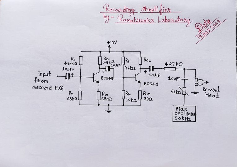
Making the Recording AmplifierCircuit
The recording current is taken from the collector of Q2
Making The Bias Oscillator Circuit
During recording, T1 and T2 operate as an oscillator at 50kHz, the erase head being used as an oscillator coil. The capacitive taps, C1, C2 and C3, also provide the necessary conditions for sustained oscillation.
Making a 3W Audio Power Amplifier
Here in my project I am using a 4 ohm 5W Loudspeaker. It is enough to produce the sound for a room. For driving the Loudspeaker I am using a 3W Class A-B push-pull power amplifier. This power amplifier can supply the max output power of 3W but my speaker require 5W power. But recreantly I do not have a 5W amplifier circuit so I am using the 3W power amplifier circuit here. The circuit consists of total 4 transistor. Transistor Q1 and Q2 forms a push-pull output stage for the amplifier. To diodes D1 and D2 also used to Bias the base of the transistor for Class A-B operation. These two diodes basically maintains the 0.7V voltage on the base terminals of Q1 & Q2 to overcame the problem of crossover distortion. Transistor Q3 is used to drive the push-pull stage. Transistor Q4 acts as a difference amplifier. The resistor R3 is a feedback resistor. The closed loop gain of the power amplifier circuit is given by following expression:
(Vout/Vin) = (R3/R4)
In my circuit, R3 = 22K & R4 = 1K
So closed loop gain of the power amplifier would be 22. The circuit operates on DC power supply of 12-22 V.
Making the Motor Speed Controller Circuit
To Control the speed of the motor of my tape recorder, I am going to use Pulse Width Modulation(PWM). For generating the PWM signal I am using the most popular 555 Timer IC. The 555 timer IC is capable of generating PWM signals. The circuit of the PWM generator has shown below. The output of the 555 timer(pin 3) is connected to the gate terminal of IRFZ44N channel mosfet. A 100 ohm resistor is also used between pin 3 of 555 timer and gate of the mosfet for limiting the gate current. You can't directly connect the motor to the output pin of the 555 timer because the motor draws more current from the source and the 555 timer can't supply enough current for driving the motor so here I have used an IRFZ44N N-channel mosfet. I am also using a 1N4007 silicon diode which is in shunt with motor and the polarity of the diode is also opposite to motor wires. This diode is a protecting diode and is called flywheel diode that is used to protect the mosfet from high voltage spikes of the motor. Motor consists of coils of wire so it acts as an inductive load to the mosfet. So the spiking of the inductor can destroy the mosfet so now you will be understood clearly that why this diode is compulsory here. I am supplying the 12V DC supply to the circuit. In my project I am using a separate 12V 2A SMPS for it. This is because my lab bench power supply is very old and can't supply the enough power for powering all circuits.
In the following circuit I am using a 10K Potentiometer to adjust the duty cycle of the PWM signal. The frequency of the PWM signal is determined my the value of C1, C2, R1 and P1.
MakingMicrophonePre Amplifier Circuit
Makingan Stereo VU Meter Circuit


_z2gGHmMYKc.jpeg)
_qeb1lijfOy.jpeg)

Comments
Please log in or sign up to comment.