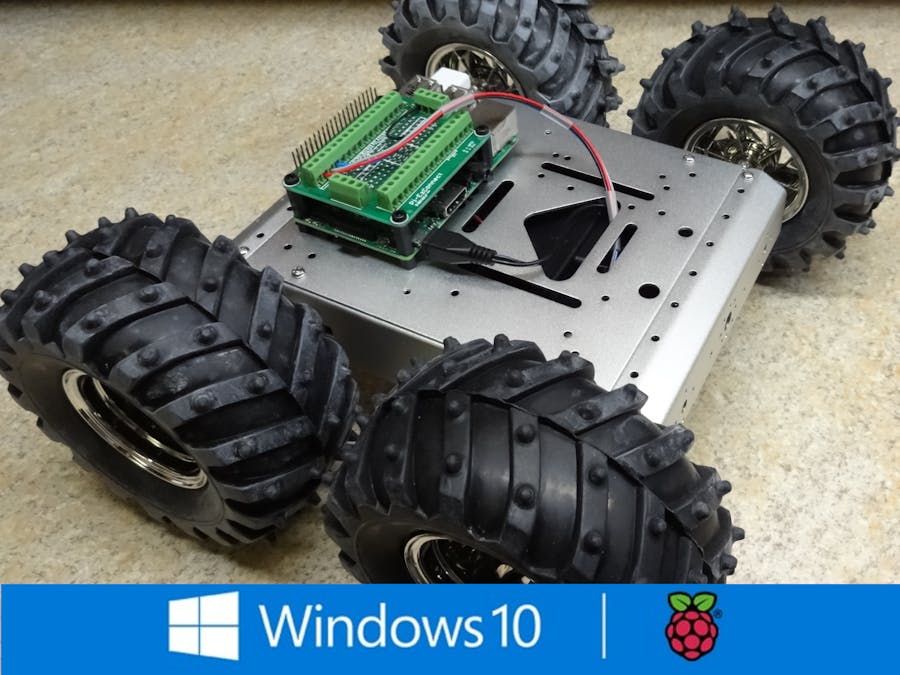
This project is intended to provide an example of how to build, power and control a wheeled chassis for your IOT project. For me, this project is the first step toward the completion of an autonomous land rover.
This project allows a Raspberry Pi 2/3 to independently control the speed and direction of four DC motors. I've chosen the ALSRobot 4WD Aluminum Mobile Robot Platform as my chassis hardware base. H-Bridges are employed for PWM speed control of the motors. Typically, PWM switching of an H-Bridge is accomplished using the GPIO pins of the Pi. However, I've chosen to offload the PWM duties to a Adafruit PWM/Servo Shield such that the PI can spend the better of its processing time on tasks such as navigation (future project).
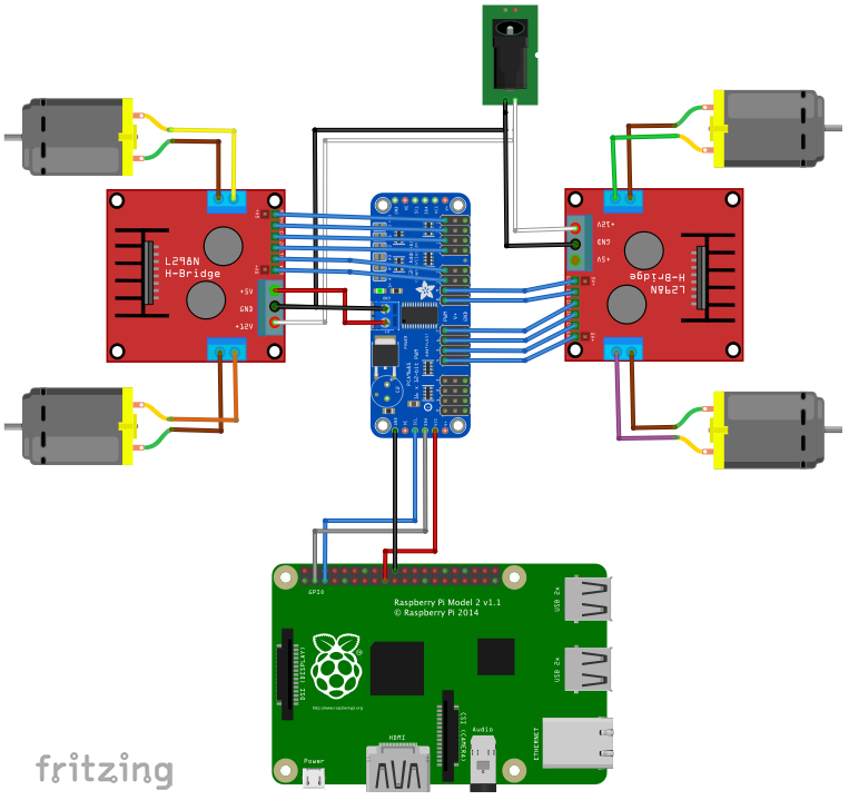
Overview:The block diagram below illustrates the DC motor control concept:
- The Raspberry Pi sends commands to the Adafruit Servo Shield via the I2C bus to turn on, off or pulse on/off at a specific rate the individual output channels of the servo shield.
- Each output channel of the servo shield is connected to an input channel of an H-Bridge controller. The two H-Bridge Circuit boards used for this project each contain two individual H-Bridge circuits, yielding a total of four H-Bridges, one dedicated to each DC motor.
- Twelve of the sixteen servo shield channels are utilized. Three channels are used by each of the four H-Bridge circuits. The three signals equivalently represent "Forward", "Reverse" and "PWM" signals.
- The Forward or the Reverse channel of an H-Bridge will be enabled corresponding to the desired direction of motor rotation. The PWM channel of an H-Bridge will be pulsed on/off at a rate that will provide speed control of the corresponding motor. Note: There are many excellent resource on the web that explain the H-Bridge and the concepts behind PWM control, I will not go into those details here.
1) Assemble the ALSRobot 4WD Aluminum Mobile Robot Platform
- Assemble the chassis per the manufacturer's instructions. Before installing the motors, solder a pair of 18 awg wires directly to each motor.
- Set the H-Bridge circuit boards in the chassis and mark the mounting holes on each corner. Drill holes in the chassis for mounting the H-Bridge circuit boards. Install M3x5mm standoff in the holes.
- I made a small wooden platform to set the robot platform on such that I could test the motors without the unit running away.... or you could just leave the tires off.... IMHO, the ALSRobot 535 chassis provides is a nice starting point for a mobile project. However, I am a little disappointed by the mechanical connection between the wheel and the motor shaft. The wheel hub slips over the motor shaft and clamps itself to the shaft with a single cap screw. This mechanism does not promote the best alignment and thus results in a bit of wheel wobble when running.
2) Install the H-Bridges
- Connect each pair of the motor wire pairs to an output channel pair of the H-Bridge circuit boards. The polarity nor the order of which motor is wired to which output pair of the H-Bridges is important at this point, just be sure you connect each motor wire pair to one of the four H-Bridge output pairs. The project code will allow us to change the motor / H-Bridge output pair and the Forward/Reverse direction of motor rotation programmatically.
- Wire the +12V and GND terminals of both H-Bridge circuit boards together. Also install to a pair of 18 AWG wires to these terminals for connection of the +12V power supply (not shown in the photo below).
- The H-Bridge circuit boards I chose to use include a 5VDC output source. Install a pair of 20 awg wires to the +5V and GND terminals of one of the H-Bridge circuit boards as a supply for the Adafruit Servo Shield (not shown in the photo below). Note: If you intend to additionally use the servo shield to control servos (or other devices), make sure the power requirement of those devices plus the H-Bridges do not exceed that of the H-Bridge's onboard 5V supply. Also note that if you choose to use an alternate 5V source to power the servo shield, you will need to tie the 5V common to the H-Bridge GND terminals as a return path for the PWM signals from the servo shield to the H-Bridge circuit boards.
- I chose to install an insulating sheet (phenolic paper) between the chassis and the H-Bridge Circuit Boards to avoid the possibility of a short circuit occurring between the chassis and the bottom of the circuit boards.
- Mount the H-Bridge circuits to the standoffs using 5mm screws.
3) Prepare the ServoShield
- For my application, I decided to install female pins and 6-pin plastic connecter housings to the servo shield to facilitate the connection of the control pins of the servo shield to the input pins of the H-Bridge circuit boards. (The crimping tool and connector kit I purchased are listed in the 'tools' section above.) Your preference for these connections may differ.
- I chose to use the last 12 channels of the (16 channel) servo shield for control signals to the H-Bridge circuit boards. Additionally, I installed 3-pin headers to the first four channels for (future) use with servos (camera pan/tilt, etc.). Solder twelve 24 AWG wires to the PWM terminals of the servo shield. Note: Make sure you wires are long enough to reach the H-Bridge Circuit Boards!
- Solder four 24 awg wires to the VCC, GND, SCL & SDA terminals of the servo shield. These conductors will be used to connect the I2C buss of the servo shield to the Pi.
4) Install the ServoShield
- You'll need to drill four more holes in the chassis to mount the servo shield. I chose to mount my servo shield in such a manner that the control wiring between the servo shield and the H-Bridges is rather short. This location also maximized the remaining space available in the chassis for future items such as battery packs.
- Mount the servo shield using M2x15mm standoffs.
- Connect the control wires from the servo shield to the H-Bridge Circuit boards (see schematic diagram below). Note: The assignment of the output pins of the Servo Shield can be changed programatically, therefore your connection order can vary from that which I have chosen.
- Connect the 5V output power from one of the two H-Bridge Circuit Boards to the 5V input terminals of the Servo Shield.
5) Connect Servo Shield's I2T interface to Raspberry Pi
- Connect the VCC, GND, SCL & SDA wires of the Servo Shield to the corresponding I2T and power points of the Pi (see Interconnection Diagram below)
- Be sure you use the Pi's 3.3V output as the VCC input to the Servo Shield or you will toast the Servo Shield and possibly the Pi!!
- I used the Adafruit Pi-EzConnect Terminal Block Breakout Hat to facilitate the connection of the I2C wires from the Servo Shield to the Pi.
The VisualStudio solution provided within the Code section (below) contains three projects.
- libPPCA9685 - Library to communicate with the Servo Shield via I2T bus. Also contains methods for commanding the Servo Shields PWM output channels continuously off, continuously on and a method for setting a channel to pulse on/off at a specific rate.
- libPWMdeviceControl - Library to control Motors and Servos. The DeviceControl class creates a thread which periodically processes up to 4 Motor objects and 16 Servo objects. Base Motor and Servo classes are defined within the library. The "Testing" section below outlines how to create, configure and assign Motor and Servo objects to the library. Processing of the user's Motor and Servo objects results in commands being sent to the servo shield channels to accomplish the requests found within the Motor and Servo object properties.
- RoverMotorTest - Test application is a quick and simple GUI for testing the functionality or the two worker libraries mentioned above. The GUI provides for position control of one servo and speed/direction control of four motors.
For testing I've connected a 5" touchscreen to the PI for display of the RoverMotorTest GUI. Power is supplied to the H-Bridges with an external 12VDC supply. I've also attached a Servo to the first output channel of the servo shield.
Some configuration may be required if your build is wired different than mine. You will find and can alter the configuration within the MainPageViewModel class of the RoverMotorTest application. Within this class the CreatePWMDevice() method is called from the class constructor. The CreatePWMDevice() method performs the following object creation, configuration and initialization.
1) Instantiate an instance of the DeviceControl class.
pwmDevice = new DeviceControl();
2) Instantiate an instance of the Motor class assigning the following servo shield channels: PWM Chanel = 15, Forward DirectionChannel = 14, Reverse Direction Channel = 13. This motor class represents "Motor 1" of my chassis. A reference to the motor class instance is assigned to the M1 property of the DeviceControl class.
pwmDevice.M1 = new Motor(15, 14, 13);
3) Repeat the creation, channel assignment configuration and class instance reference assignment for the other three motors.
       pwmDevice.M2 = new Motor(9, 8, 7);
       pwmDevice.M3 = new Motor(10, 11, 12);
       pwmDevice.M4 = new Motor(4, 5, 6);
4) Instantiate an instance of the Servo class assigned to channel 0 of the servo shield. Assign a reference to the servo class to the S1 property of the DeviceControl class.
pwmDevice.S1 = new Servo(0);
5) Call the initDevice() method of the DeviceControl class instance, specifying the Adafruit Servo Shield's default I2C bus address of 0x40.
await pwmDevice.initDevice(0x40);
The application should now be configured ready to be compiled and deployed to the PI. The GUI can be used to individually assign a speed, direction and command each motor to start/stop. The GUI also provides a numeric entry field for entering a rotation angle for a servo connected to channel 0 of the servo shield.
I hope you find this project both informative and helpful toward a successful build of your own mobile IOT project.
H-Bridge part for Fritzing interconnection diagram curtesy of yohendry.


Comments
Please log in or sign up to comment.