


Hardware components | ||||||
 |
| × | 1 | |||
_ztBMuBhMHo.jpg?auto=compress%2Cformat&w=48&h=48&fit=fill&bg=ffffff) |
| × | 1 | |||
Software apps and online services | ||||||
 |
| |||||
 |
| |||||
 |
| |||||
Hand tools and fabrication machines | ||||||
 |
| |||||
 |
| |||||
 |
| |||||
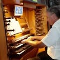
The Cantor analog organ had a serious breakdown some time ago and was converted into a MIDI console for controlling software like VPO (virtual pipe organ). Then, however, only the manual keyboards (manuals) and the pedal keyboard were connected through two interfaces constructed on the ATMEL89S52 chip connected to two separate MIDI outputs, one on the right and one left under the keyboards. It was a cost effective solution, but quite a hassle to connect a computer with GrandOrgue (aka Hauptwerk).
You had to use two cables and two MIDI-USB interfaces or one double.
In addition, the board with the main registers and group registers were not connected at all. Organ voices had to be changed on the monitor screen. The computer and monitor with GO had to be placed outside the organ, which also reduced the comfort of the playing and took up space.
I decided to connect the registration switches and group registries, and hide the computer inside the wooden casing of the organ. If it were possible to enable voices with registers and the GO was started from autostart, the screen monitor would be redundant and could be dispensed with. Ultimately, connect it only when changing the software configuration.
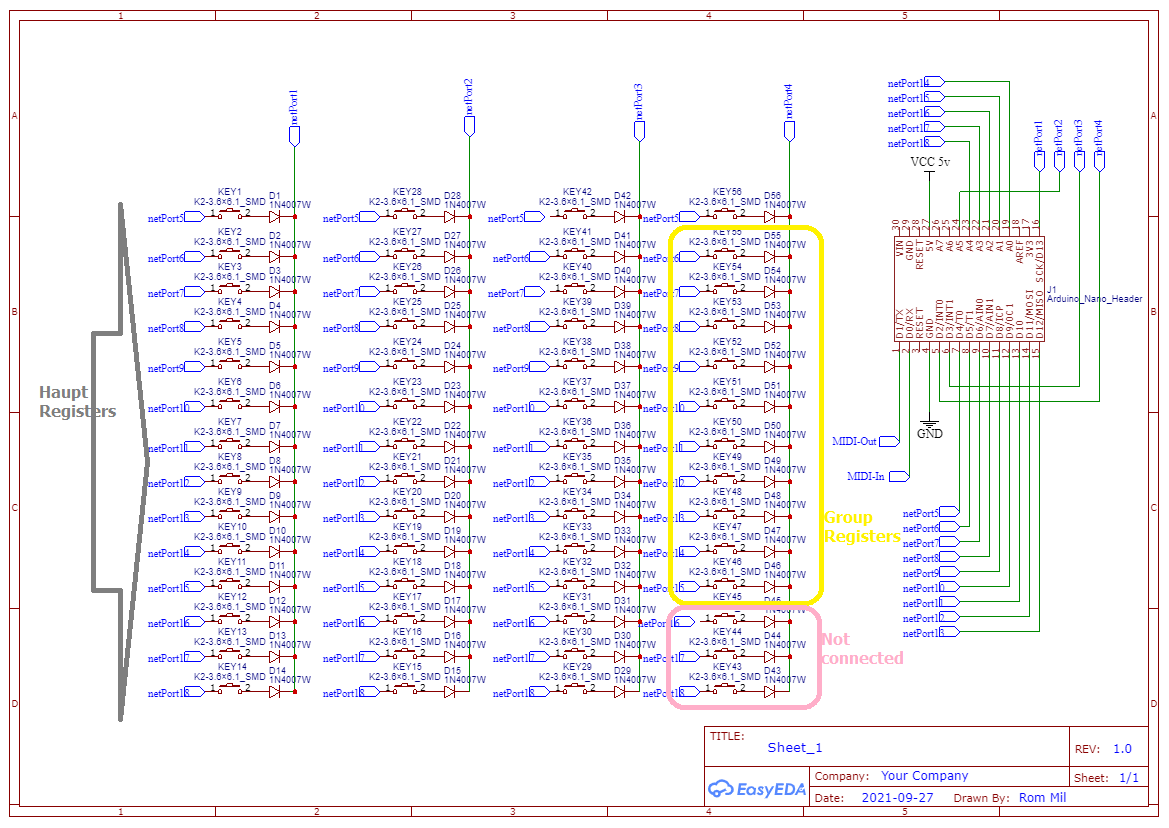
I decided to use the Arduino Nano to connect the registers. I wrote the program in the Arduino IDE using the Surface_Controll library (https://github.com/tttapa/Control-Surface). In order to connect 39 switches to a limited number of Arduino Nano pins, I needed to create a matrix with diodes. In this case, it was relatively easy to construct the matrix in the organization of 4 columns on the 14th row (3 panels of register switches plus switches for ten group registers).
The matrix columns were attached to the pins 13, A5, 3, 2 and lines up to 4, 5, 6, 7, 8, 9, 10, 11, 12, A0, A1, A2, A3, A4. In order for pin 13 to work in matrix mode, you had to desolder the LED that is standard in the Arduino Nano on this pin.
TX and RX arduino pins are respectively the output and input of the MIDI signal on the TTL level. Arduino forwards received MIDI messages from pin RX to TX. To the RX pin I connected the MIDI output from the 89S52 chip that supports the pedal keyboard, and the TX pin was connected via a 220 Ohm resistor to the first MIDI-In MERGER. The second MIDI-In MERGER has been connected to the MIDI output from the second 89S52 chip that supports two manuals (handheld keyboards). I connected the Merger's MIDI output to the MIDI-USB interface made on the basis of the reprogrammed Arduino UNO. https://doremifasollasi.wordpress.com/jak-przerobic-arduino-uno-w-interface-midi-usb/
The ATMega328p processor on board the Arduino UNO has the TX tip disconnected by bending it upwards, so that there is no conflict with the MIDI signal from MERGERA which affects pin 1 (TX) of the Arduino UNO. I programmed this ATMega328p as a MIDI message decoder. It receives noteON and noteOFF messages on channel 13 and turns the appropriate output LEDs on or off. The LED on pin 13 lights the noteON message with a value of 71. This is sent by the GrandOrgue program after loading the samples and highlighting the Noise Motor register. A glowing LED connected to pin 13 of the Arduino UNO signals the completion of loading the samples and the GrandOrgue is ready to work.
Lenowo computer (i3 / 8GB RAM) with openSuse Linux and VPO - GrandOrgue software was taken out of its tin casing and mounted in parts in a wooden Cantor organ cabinet.
I connected the computer's audio output to an existing original amplifier that works with 4 speakers mounted in the organ cabinet.


Comments