


_HRKYofTb1T.png?auto=compress%2Cformat&w=900&h=675&fit=min)
Hardware components | ||||||
_ztBMuBhMHo.jpg?auto=compress%2Cformat&w=48&h=48&fit=fill&bg=ffffff) |
| × | 1 | |||
 |
| × | 1 | |||
Software apps and online services | ||||||
 |
| |||||
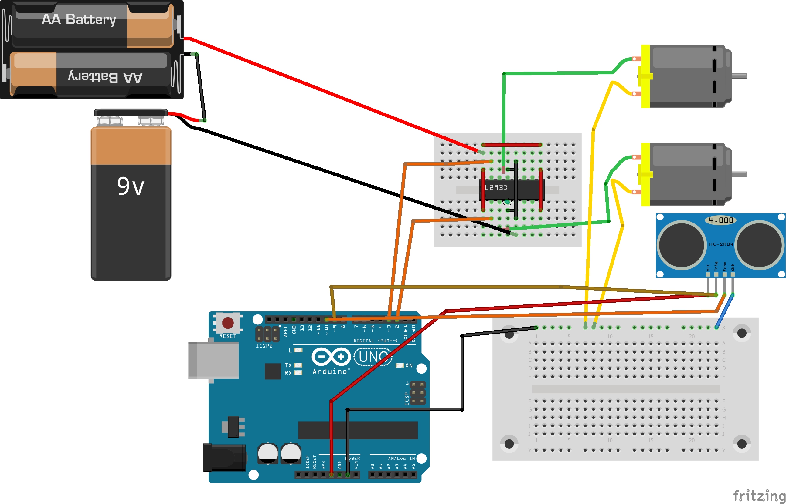
The below diagram displays the ultrasound sensor and the Arduino. The model made was for presentation purpose only.
IntroductionLevel indicator is mostly used in all industrial sectors. We can also implement the same for small scale working or domestic purposes. We have constructed a fluid level sensor which helps us to read continuous data. It gives us the value of how much fluid is occupied in the tank. The system we have created is a feedback system which not only gives us a the amount of fluid occupied but also controls it by using pump.
The above figure is a simplified block diagram of the system I have created. The Arduino is the micro controller that we are using. The ultrasound sensor HC-SR04 is connected to Arduino. The sensor is mounted on the top of the tank. I have used two submersible pumps for model. The submersible pumps are uni-directional, i.e., it can transport fluid from one direction to another only. We could use a bi-directional pump which can be operated in both directions. Both the pumps get signal from the Arduino. The pumps requires 12v to operate, therefore we have to use a motor driver too. (The motor driver is not shown in the block diagram.)
WorkingFor easier understanding, we'll divide the model into different sections:
- Sensing system
- Control system
The sensing system has an ultrasonic sensor HC-SR04. The ultrasonic range goes above 20 kHz. This sensor has a Transmitter and a Receiver. The Transmitter produces an frequency of 40 kHz; this ultrasonic wave is bounced back from the fluid level and is received by the receiver. This sensor has 4 pins: ground is given to Arduino ground and VCC can be +3.3v or 5v. The trigger pin is used to give a trigger signal to the transmitter. The echo pin is used to receive the echo from the ultrasound. From this we get a time period of the ultrasound to produce and receive. We need to convert time into distance. The following is shown below:
 duration = pulseIn(echoPin, HIGH);
// Calculating the distance
distance= duration*0.034/2;
The Arduino receives the data from the sensor and then it gives the desired signal to the pumps. We can set our given level from the code. If the level crosses the given threshold the pump in the tank is given a signal and it starts to pump the water out of the tank until its under the threshold. When the level falls below the mentioned threshold the pump in the reservoir starts pumping fluid to the tank. The tank and only one pump will be used.
Future ImprovementsWe can improve the efficiency of the project by the following:
- We can use a bi-directional pump which can be located outside the tank, then only one pump have to be used.
- We can display the result on an OLED or on a LCD screen.
- We can also store data on cloud if connected to IOT.
- We can control the fluid level and also check the fluid level from an application if connected to IOT.
- We can also provide a safety buzzer when the tank overflows, we can also modify the code to avoid overflow of the tank.


Comments
Please log in or sign up to comment.