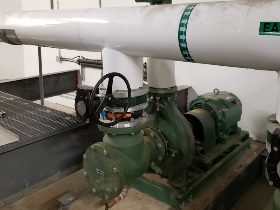
In the project that I'll be depicting below I'll demonstrate how some aspects of a cooling tower can be controlled autonomously. There are some system errors that don't require human intervention and we will be focusing on that part in this project. Before we begin a few words about what exactly is a cooling tower.
What Is A Cooling Tower?A cooling tower is a specialized heat exchanger in which air and water are brought into direct contact with each other in order to reduce the water’s temperature. As this occurs, a small volume of water is evaporated, reducing the temperature of the water being circulated through the tower.
Water, which has been heated by an industrial process or in an air-conditioning condenser, is pumped to the cooling tower through pipes. The water sprays through nozzles onto banks of material called “fill, ” which slows the flow of water through the cooling tower, and exposes as much water surface area as possible for maximum air-water contact. As the water flows through the cooling tower, it is exposed to air, which is being pulled through the tower by the electric motor-driven fan.
When the water and air meet, a small amount of water is evaporated, creating a cooling action. The cooled water is then pumped back to the condenser or process equipment where it absorbs heat. It will then be pumped back to the cooling tower to be cooled once again.
The above pictures depict a basic idea of how a cooling tower works and the error messages I sometimes get on the control panel.
The video below depicts hot water flowing into the top of the honeycomb of the cooling tower but as you can see the amount of water needed to flow correctly down the honeycomb has to reach the top of the pvc pipes which is clearly not happening and that could be a problem.
TheParts:
For this project will be using the STM 32 Discovery board provided to us by Helium and a water level sensor. A water level sensor is a simple device that is used to measure the level and the volume of water inside a container, will be using a conductive-type water level sensor, where the change in resistance of parallel wires over varying depths of water is converted to voltage.
WaterLevel Sensor Setup:
S: A0
+: 5v
-: Ground
SetupDiagram:
(Aboveyou see a picture of the Serial monitor output)
(Below is a picture of the sensor wiring)
HeliumConsole (Setup):
Now will be setting up a device on the Helium Console, its a fairly straight forward and simple process. Lets get started.
Step 1:
First thing we do is register for a free account: https://www.helium.com/console
Step 2:
Now were going to setup a device to connect with the Helium Network later on.
In the picture below you can see that I've already setup a device for this specific project.
Click on + Add New Device, you'll be prompted with this window.
Once the device is ready you'll see it appear on the device menu. Click on the device name to open the device details menu.
As you see with the above picture here you are given all the information you'll be using later on to transmit information to the Helium Network. You can also add a label to your device by simply scrolling down to Attached Labels and clicking on + Add Label, this way you can better organize your devices.
Helium Network (Setup):
Now will be connecting the device we just created with the Helium Network and start transmitting information. For this part will be using a Hardware-As-A-Service session to depict how the Helium Network functions, a big thanks to "HolyChris" with "Project Kerosene" for providing a platform to run our code on, check out the project kerosene on github https://github.com/HolyChris/ProjectKerosene.
Step 1:
First we need three things from the Device Details Console to be able to run our code and get live data. Go back to the Helium Console window, click on Devices and then click on the device you created before. For our code example we need three things, Device EUI, App EUI and App Key. Now click on the arrows next to the keys to change the format to least significant bit (lsb) or most significant bit (msb).
The Arrows are the ones in the blue circle, for Device EUI and App EUI once you clicked on the arrows click on the arrows depicted in the green circles to change to lsb format.
Step 2:
Now we start a session to test out our device, click on this link to request a session:
https://rerobots.net/sandbox/helium/gy4Z4kRfgn4yAuavaWeGWQjjF1WJeQt6
Step 3:
On the session window we just opened were shown a live view of the devices that are online and a window with the code will be using, on the bottom you can also see we have a few buttons like "build", "flash", "download source file" etc..
On line 63,67, 71 is where we need to input our device info in the correct format, Device EUI, App EUI and App key.
Device EUI : lsb
App EUI : lsb
App Key : msb
Once were done with that we hit the "flash" button and on the console window on the right hand side and we see the code upload to the board. If there are no errors and the console window says "success" in a little while live data will be streamed to our Helium Console window.
As you can see in the picture below the console shows us how many packets were transferred and when.


Comments
Please log in or sign up to comment.