The MAX32620 FTHR is an incredible device that can be used to control pretty much any household electrical appliance, from a coffee machine all the way to an electric heater. In this project, I'll show you how to control an electric heater using the MAX32620, a relay, and the GUI we will create.
Step 1:Since we're going to use Arduino IDE, the first step is to upload the JSON Maxim package. To do that, follow the steps provided below.
- For Windows, and Linux, go to File->Preferences. For Mac OS, go to Arduino->Preferences.
- In the Dialog box, locate Additional Boards Manager URLs field, paste the following URL and click OK.
https://raw.githubusercontent.com/maximintegratedmicros/arduino-collateral/master/package_maxim_index.json
- Go to Tools->Board->Boards Manager...
- In the search field, type "maxim".
- Select Maxim's 32-bit Microcontroller and click Install.
- Once the installation is completed, close the Boards Manager.
- Go to Tools->Board. In the section Maxim ARM (32-bit) Boards, select your board from list of Supported Boards.
- Plug in your board and under Tools->Port select the appropriate serial port for your board.
- Go to Tools->Programmer and select DAPLink.
The second step is to verify that everything works well between the MAX32620 and Arduino IDE. Follow the steps below to upload your first blink sketch.
- In the Arduino IDE, go to File->Examples->01.Basics->Blink.
- Click the Verify button or go to Sketch->Verify/Compile.
- Click the Upload button or go to Sketch->Upload.(Requires USB Write access; Details here.)
- If you are using a board with Bootloader, it will reset itself and start running the application code. For non-Bootloader version, you need to press the Reset button to run.
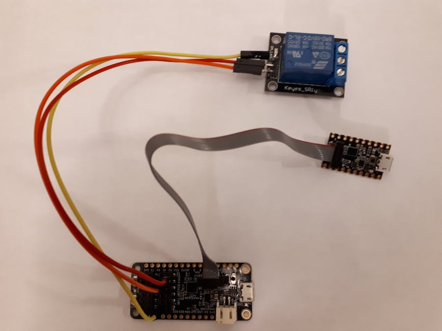
The third step involves connecting the relay to the board. For that, we will use this incredible feature of the port connectors with PMOD compatibility.
We will use DIO2 for the relay signal, which is depicted on the upper left side of the pin description. For power and ground, use the pins PVIO and GND.
Step 4:Now we're going to upload the Arduino sketch I've provided, and once the uploading is finished, we press the reset button on the MAX32620 FTHR.
Remember: Every time you upload a new sketch, you always have to press the reset button so it starts running the new program.
Step 5:Next, we're going to download an application called Processing. This program will help us create a GUI for our sensor. You can download the software from this link: Processing Download Page.
Step 6:Once the zip file has been downloaded, we unzip it and install Processing.
In this step, we're going to import the library we need to use for our LED on/off example. The library we're going to use is called ControlP5. To install new library from menu, go to: Sketch -> Import Library -> Add Library.
Now open Processing and put in the code I provided for Processing (Processing GUI Code), and then after we're done putting in the code, click on the run button that's on the left side of the programming environment window.


_1x_bGT19vVAby.png?auto=compress%2Cformat&w=40&h=40&fit=fillmax&bg=fff&dpr=2)
Comments
Please log in or sign up to comment.