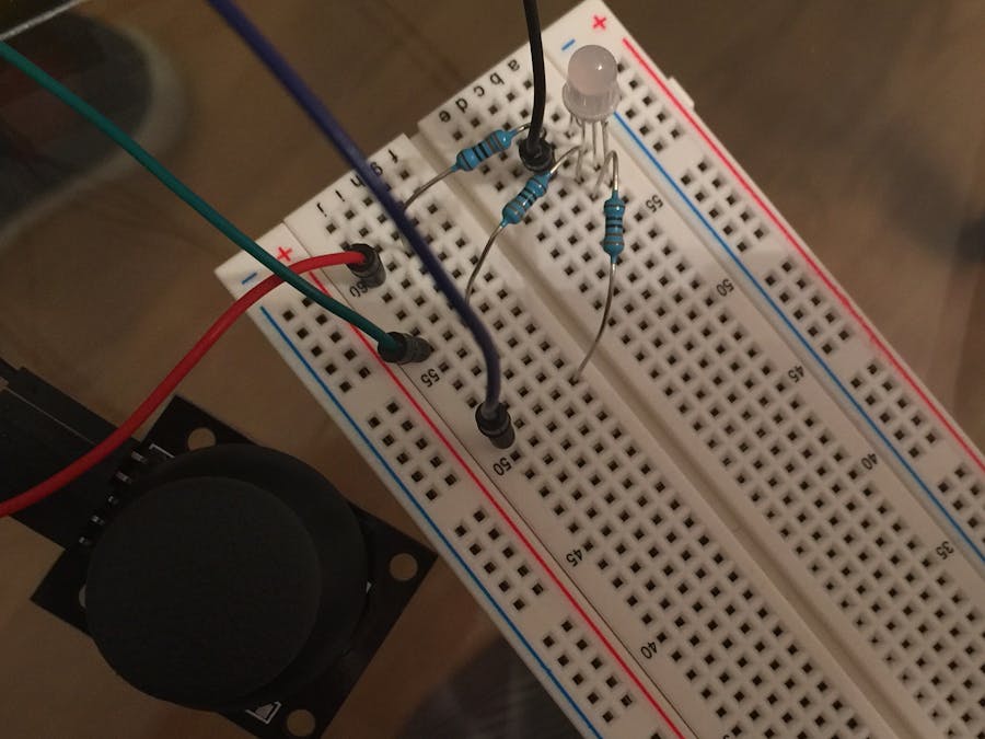
This project uses a joystick to control an RGB LED. When the joystick is at a certain position, the LED changes colors. In my project, the led colors are green, yellow, orange, blue, and pink. The reason I made this project is simple, to improve my Arduino programming/ hardware skills. This is a very easy and fun project to do.
The joystick is connected to the 5 volt connection and ground. The X axis of the joystick is connected to A0, and the Y axis is connected to A1. The RGB LED is oriented in a way that from left to right the pins are red, ground (the longest pin), green, and blue. The red is connected to pin 9, green to 10, and blue to 11 (make sure you use a minimum of 330 ohm resistor, or your led will be destroyed). The pins that the LED are connected are special because they have the ~ character on them. This means PWM or Pulse Width Modulation. You are able to control the duty cycle on these pins allowing you to control the specific color of the RGB LED. For a Common Anode RGB LED connect to 5v instead of ground.
The reason I include the two "contributors" on this page is because I sat down today not knowing how to program an LED or a joystick, and their sites were very helpful. I mashed some code together, and ended up with this.


_wzec989qrF.jpg?auto=compress%2Cformat&w=48&h=48&fit=fill&bg=ffffff)


Comments
Please log in or sign up to comment.