Update: Good news! There is now a new version of EdiBot: EdiBot 2.0.
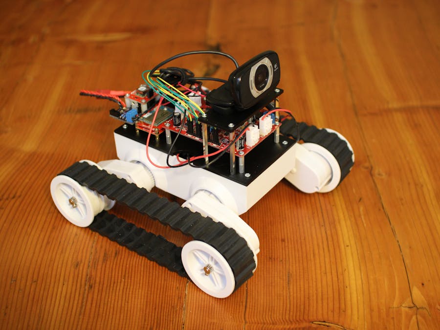
The EdiBot is a robot built to demonstrate the Intel Edison and SparkFun Blocks. It relies on the Arduino Block to control the motors while the Edison handles the vision processing tasks. The robot finds any red objects and drives toward the largest one. If the red object is too large in the field of vision, the robot backs up.
Step 1: Order and Build the Power BoardYou will need a board that can pass direct battery power to the Rover 5 Board (to power the motors) and step the voltage down to 4.2 V to power the Edison and Arduino. I've created a board on OSH Park to do just that:
https://oshpark.com/shared_projects/YDhDBhlM
You can order that or create your own. The schematic and layout (Eagle) can be found in the GitHub repository for EdiBot.
Note: The VSEN signal does not work! The idea was to have the Arduino sense the voltage at the REF pin of the TL431 and turn on the Low Battery LED once the voltage reached a certain level. However, without power, the ADC pins pull the voltage at REF to a level that prevents the MOSFET from turning on, which means you don't get power! If I make a revision of the Power Board in the future, this will be fixed.
You will want to build the board with the following components:
- R1: 200k
- R2: 130k
- R_TRIM: 1.65k
You will also want attach a Deans connector through some wire to VBATT and GND on the Power Board. This will allow the robot to be powered by a LiPo battery.
Solder a 6-pin, right-angle header into the FTDI port on the side of the Arduino Block. Using a 3.3V FTDI breakout, program the Arduino Block with the StandardFirmata using the instructions here:
Step 3: Construct the Block StackUsing the Edison Hardware Pack (e.g. M2 screws, nuts, and standoffs), attach the Edison to the Arduino Block and then to the Base Block. The stack should be:
- Edison
- Arduino Block
- Base Block
Note: Do not add a standoff or nut on the mounting hole by the TX pin on the Arduino Block, otherwise you might short an RX via to ground and prevent UART communications.
You will need something to mount all of your hardware to the Rover 5 chassis. You can drill holes in any material, but if you have access to a laser cutter, it makes the lining up the mounting holes much easier.
Download the following vector art file (or PDF) and cut the shapes on a laser cutter.
Mount the Rover 5 Board, Edison Block stack, and the Robot Power Board to the bottom plate. Notice that the Rover 5 Board uses the standoffs that came in its package, the Edison stack uses 2 standoffs from the "Edison Hardware Pack," and the Power Board uses #4-40 3/8 inch plastic standoffs.
Run power wires from Vbatt and GND on the Power Board (screw terminals) to Vbat and GND of the Rover 5 Board (screw terminals). I used 2x 22 AWG stranded wires for each connection, since a single motor stall can draw a few amps.
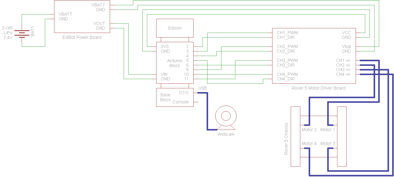
Using F/F jumper wires, connect the following from the Robot Power Board to the Arduino Block:
- VOUT → VIN
- GND → GND
Because the VSEN pin does not work, do not connect anything to it or the WARN pin. For future reference, VSEN is supposed to go to A0 (Arduino Block) and WARN is supposed to go to pin 8 (Arduino Pin).
Again using F/F jumper wires, connect the following from the Arduino Block to the Rover 5 board:
- 3V3 → VCC (any)
- GND → GND (any)
- 3 → CH1: PWM
- 2 → CH1: DIR
- 9 → CH2: PWM
- 4 → CH2: DIR
- 11 → CH3: PWM
- 6 → CH3: DIR
- 10 → CH4: PWM
- 5 → CH4: DIR
Attach a webcam to the plate with a 1/4 inch screw.
Add the 4 standoffs on the sides of the Rover 5 Board, and attach the webcam plate. Use the long standoffs that came with the Rover 5 Board.
Connect the Webcam to the Edison's OTG port via a USB micro-A adapter.
Place a LiPo battery (or the battery pack that came with the Rover 5) in the Rover 5 Chassis.
Use some #4-40 screws to mount the hardware to the chassis. You will likely need to remove the Power Board to get to the back screw holes.
Route the motor cables through the semicircle openings on either side of the plate. Connect the motors to the following on the Rover 5 Board:
- Front right motor → CH1
- Front left motor → CH2
- Rear right motor → CH3
- Rear left motor → CH4
Route the battery cables through the semicircle opening on the back of the plate.
Follow the instructions in the link below to install Ubilinux on your Edison. Don't forget to wait at least 2 minutes after the installation!
https://learn.sparkfun.com/tutorials/loading-debian-ubilinux-on-the-edison
Step 10: Install LibrariesLog in to the Edison over a serial console or SSH with the credentials:
Username: edison
Password: edison
Gain superuser privileges:
su
Password: edison
Follow the instructions in the Ubilinux tutorial to enable WiFi:
https://learn.sparkfun.com/tutorials/loading-debian-ubilinux-on-the-edison#enable-wifi
Update apt-get:
apt-get update
Install prerequisite libraries:
apt-get install libopencv-* apt-get install python-opencv apt-get install python-pygame apt-get install python-scipy apt-get install python-serial apt-get install python-setuptools apt-get install python-pip
Install Python modules:
pip install svgwrite
Install SimpleCV:
git clone https://github.com/sightmachine/simplecv cd simplecv python setup.py install cd ..
Clean up packages to free up some space:
apt-get autoclean apt-get clean apt-get autoremoveStep 11: Run EdiBot Code
Download the repository:
git clone https://github.com/ShawnHymel/EdiBot cd EdiBot
Run the Python program:
python Ball_Chase.py
You will want to plug the battery into the Power Board and turn the switch to ON. This provides power to the motors.
Step 12: Play With Your RobotHold up a any red object to the robot's webcam. The robot will attempt to chase the object!
If you want the Ball_Chase.py program to run on startup, we need to blacklist the uvcvideo module and load it right before we run the script (otherwise, the webcam does not run properly):
nano /etc/modprobe.d/fbdev-blacklist.conf
Add the following line at the bottom of the file:
blacklist uvcvideo
Modify rc.local to load the uvcvideo module and run the Ball Chase program on boot. Open the rc.local file:
nano /etc/rc.local
Add the following lines right before the "exit 0" line:
/sbin/modprobe uvcvideo python /home/edison/EdiBot/Ball_Chase.py &
The '&' allows the script to run in the background. Reboot the Edison and let it loose to chase red things!
Note: You will need to perform a hard reboot (remove power and turn it back on it). Otherwise, the webcam USB drivers will not load. Also, it might take a while for Linux to boot up. Wait about 30 seconds for the webcam light to turn on after providing power to the EdiBot.


_3u05Tpwasz.png?auto=compress%2Cformat&w=40&h=40&fit=fillmax&bg=fff&dpr=2)
Comments
Please log in or sign up to comment.