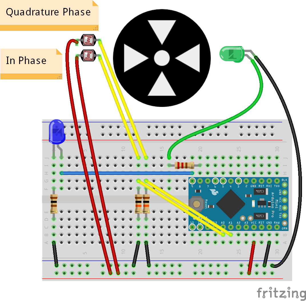
This will make a quadrature encoder demo (or the world's worst dimmer switch). I originally created this project to demonstrate how optical encoders work as part of a YouTube video for SparkFun.
Print Encoder WheelHead to https://www.thingiverse.com/thing:1147656 and download the encoder disc files. Use a 3D printer to print the disc with 5 holes. I recommend scaling the print up to 3x size.
Use a bolt, dowel, etc. to allow the encoder wheel to spin. Mount it to some kind of structure. I used an Actobotics part.
Build CircuitFollow the Fritzing diagram to connect the various components.
Mount the photocells on the opposite side of the encoder disc as the LED. You want the LED to shine through the holes in the encoder disc.
Upload CodeCopy the code to an Arduino sketch and upload it to the Pro Mini.
Run!As you spin the encoder disc in one direction, it causes the blue LED (listed as "lamp" in the code) to get brighter. Spin the disc in the other direction, and the LED gets dimmer.
Going FurtherThis is obviously a project for demo purposes only. You can buy real encoders that perform much better (and probably for less money, too). If you want to challenge yourself, see if you can make the encoder respond to both edges on the in-phase detector, instead of just a falling edge.


_3u05Tpwasz.png?auto=compress%2Cformat&w=40&h=40&fit=fillmax&bg=fff&dpr=2)
Comments
Please log in or sign up to comment.