

Hardware components | ||||||
| × | 1 | ||||
| × | 1 | ||||
| × | 1 | ||||
| × | 1 | ||||
 |
| × | 1 | |||
| × | 1 | ||||
 |
| × | 1 | |||
 |
| × | 1 | |||
 |
| × | 2 | |||
| × | 1 | ||||
Software apps and online services | ||||||
| ||||||
 |
| |||||
Hand tools and fabrication machines | ||||||
 |
| |||||
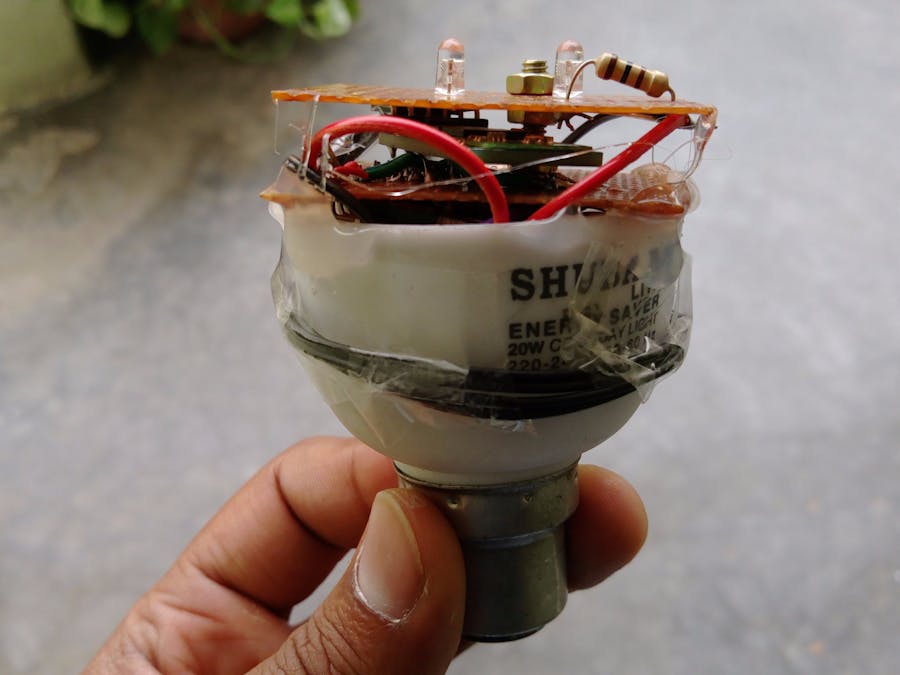
Here we've built a Bluetooth Controlled Smart (kind of) LED Light. The Light being built using old CFL bulb body can be plugged directly into ordinary bulb sockets. Once plugged into the socket, Bulb is ready to receive commands. Then, the user would be able to send ON/1 or OFF/0 commands over a bluetooth app to switch the Bulb ON or OFF
DemoHow it works?The brains of our smart bulb is ATtiny84 Microcontroller working with a HC05 bluetooth transceiver which receives bluetooth commands from a smartphone. When the HC-05 module receives some data it transfers it to ATtiny84 over Serial Pins (10 and 9, the pins are defined in software and can be changed). The Microcontroller compares the received data with an if condition, if the received data contains "1", uC switches the pin 3 HIGH which further switches ON the transistor thus switching the two LEDs ON. The power is supplied from a 220VAC to 7VDC power supply through 7805 (5V regulator) to uC and HC-05.
Lets Build!To keep the construction smaller, two separate boards are built-
- 1st with Power Regulator, Microcontroller, Bluetooth connector & Transistor Switch
- 2nd with Dual LED circuit with 100ohm resistor
Make connections as per Diagram:
Build 1st Board
This board includes 7805 regulator, ATtiny84 Microcontroller, Bluetooth module connectors & Transistor Switch:
If you don't like working on perfboards, I've designed PCBs you can get fabricated:
You can download the Gerber Files at the bottom.
Build 2nd Board
The 2nd board consists of two LEDs connected in Parallel and in series with 100ohm resistor. This boards takes input from the 1st board transistor switch.
Well, you can't program the ATtiny84 microcontroller directly just by plugging in Arduino ATmega328 socket. You need to follow the method as explained below
Installing ATtiny support in Arduino IDE
- Open preferences dialog and find the “Additional Boards Manager URLs” field near the bottom of the dialog
- Paste the following url into field - https://raw.githubusercontent.com/damellis/attiny/ide-1.6.x-boards-manager/package_damellis_attiny_index.json
- Click the OK button to save your updated preferences
- Open the boards manager in the “Tools > Board” menu
- Scroll to the bottom of the list; you should see an entry for “ATtiny”
- Click on the ATtiny entry. An install button should appear. Click the install button
- The word “installed” should now appear next to the title of the ATtiny entry
- Close the boards manager. You should now see an entry for ATtiny in the “Tools > Board” menu
Make Connections with Arduino UNO
We'll be using Arduino as ISP to program our ATtiny 84/ATtiny85 (Connections are similar for both)
#include <SoftwareSerial.h>  //Software Serial Port
#define RxD 9
#define TxD 10
#define DEBUG_ENABLED  1
SoftwareSerial blueToothSerial(RxD,TxD);
int led = 3;
void setup() {
pinMode(RxD, INPUT);
pinMode(TxD, OUTPUT);
setupBlueToothConnection();
pinMode(led,OUTPUT);
digitalWrite(led,HIGH);
}
void loop() {
int count=0;
char recvChar;
while(1){  //check if there's any data sent from the remote bluetooth shield  if(blueToothSerial.available()){
    recvChar = blueToothSerial.read();
    if(recvChar == 1){
    digitalWrite(led,HIGH);
    }
    else{
    digitalWrite(led,LOW);
    }
      }
     }
 }
void setupBlueToothConnection() {
blueToothSerial.begin(9600); //Set BluetoothBee BaudRate to default baud rate 38400
blueToothSerial.print("\r\n+STWMOD=0\r\n"); //set the bluetooth work in slave mode
blueToothSerial.print("\r\n+STNA=HC-05\r\n"); //set the bluetooth name as "HC-05"
blueToothSerial.print("\r\n+STOAUT=1\r\n"); // Permit Paired device to connect me
blueToothSerial.print("\r\n+STAUTO=0\r\n"); // Auto-connection should be forbidden here
delay(2000); // This delay is required.  //blueToothSerial.print("\r\n+INQ=1\r\n"); //make the slave bluetooth inquirable
blueToothSerial.print("bluetooth connected!\n");
delay(2000); // This delay is required.
blueToothSerial.flush();
}
Upload the code and connect the board 1 with board 2. Now Connect the board 1 7V input to the 220VAC-7VDC Power supply. Insert the boards in CFL body and fix using Hot Glue Gun and Nuts/Bolts.
Download the Android App
Download the app from Play store here https://play.google.com/store/apps/details?id=com.giumig.apps.bluetoothserialmonitor
You are Done!Launch the app, pair your HC-05 and start the switch mode. Now you can press the button on the app to switch the LED On or Off.
What's Next?Next, we'll be adding LDR Light Sensor to our Smart LED to automate the Switching process + a temperature sensor could be added to receive temperature data on your smartphone.
_eESPu0jxgc.png)


_eESPu0jxgc.png)
Comments