


Hardware components | ||||||
| × | 1 | ||||
| × | 1 | ||||
 |
| × | 1 | |||
 |
| × | 1 | |||
 |
| × | 1 | |||
Software apps and online services | ||||||
 |
| |||||
 |
| |||||
 |
| |||||
The goal of this project was to create a space where an individual can maximize their focus capabilities, even if just for a short period of time. It is aimed at ADD/ADHD sufferers, procrastinators, and generally anyone who may benefit from a focus aid!
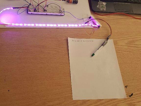
The system is simple. A single high intensity LED strip placed at the top of your work communicates with a special pen (just a pen with a button embedded in it) through a microcontroller, and when it senses that you have not been "working" (using the pen) for a certain amount of time (mine is set to 10 seconds), it turns the LED strip on... ideally the flash will distract you from your distraction. And bring you right back on task!
If you want more information before beginning, check out our infomercial for this project!
Step 1: Collecting MaterialsI built this system with a chipKIT WF32 and LabVIEW. I have found the WF32 to be an excellent little microcontroller, and between its built in wifi capabilities and seamless interface with LabVIEW, it has a myriad of practical applications.
Total cost of this project came out to about $100 (assuming you do not currently own any of the materials).
Step 2: Setting up the WF32 and LabVIEWBefore assembling the circuit, you first must make sure that LabVIEW and the WF32 are set up properly and communicating. Below is a great tutorial that details how to get your WF32 set up with LabVIEW. You will have to use something called LabVIEW Makerhub to get the board to communicate but if you follow the setup guide below it should be pretty straightforward. Once you have everything working, we can get started on the circuit!
NOTE: In the materials list I said LabVIEW is coded in Go. This is not true to my knowledge, but I did not see the the language that Google says LabVIEW is actually coded in listed.
According to Wikipedia and Google LabVIEW is actually "a system-design platform and development environment for a visual programming language from" National Instruments. The graphical language is named "G" (not to be confused with G-code)"
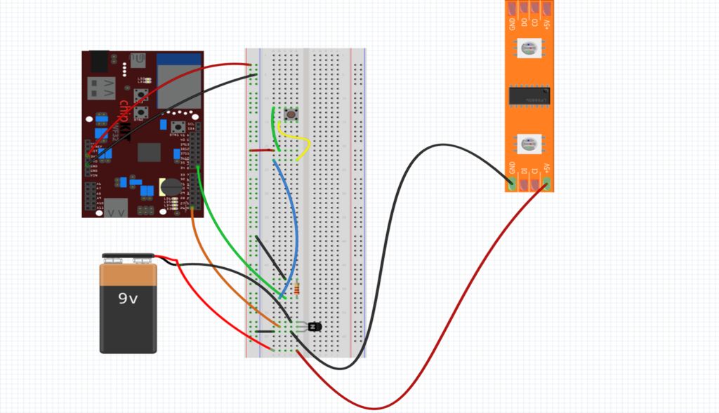
Step 3: Assembling the CircuitThe premise of the circuit is basically a push button wired into pin 8 on the WF32 as the input, then the middle leg of the transistor is connected to pin 26. The left and right legs are then connected to a 9 volt battery, which in turn is connected to the led strip.
Step 4: Building the PenTo build the pen, simply take your clicky pen and unscrew the top. Then take out the white tube inside (which holds the ink) and wrap a small strip of duct tape around it about an inch down. Remove the spring from the bottom of the pen, and place it over the top so that it rests on the duct tape strip. Then re-insert the white tube (with spring on top instead of bottom) into the pen body. Finally, take the small push button and tape it face down to the top of the outer pen body. Attach two longer wires to the button, and optionally add some plastic/cardboard/ect wrapped around the top to secure the wires to. This reduces strain and limits the chances of breaking the connection to the button.
The wires leading from the pen are attached to the same terminals on the circuit as the button was.
Step 5: Upload CodeOnce everything is all set up, you can upload the code.
Make sure you select the correct COM port, as well as digital input channel 8, and digital output channel 26. I have included my code below, but feel free to modify: it!
Step 6: Try it Out!Once the code is uploaded, click "Run" on LabVIEW and give it a go!


_3u05Tpwasz.png?auto=compress%2Cformat&w=40&h=40&fit=fillmax&bg=fff&dpr=2)
Comments
Please log in or sign up to comment.