The 555 timer is a simple, yet multifunctional IC found in many popular devices such as speed controllers, LED dimmers, or any variable voltage controller. This guide shows how to build a circuit using a 555 timer in monostable mode to drive components at variable voltages.
BoM
- NE555 Timer
- RPF40N10/SMP40N10 MOSFET
- TO-220 Heatsink
- Buck Converter
- SPDT Slide Switch
- SP3T Slide Switch
- 10k/50k/100k Potentiometer
- 1uF Capacitor
- 0.1uF Capacitor
- 0.01uF Capacitor
- 10nF Capacitor
- Screw Terminals [x2]
- 1N4007 Diode [x2]
- 1k Resistor
- 470R Resistor
- DIP8 Socket
- Perfboard
Tools:
- Soldering Iron
Pulse Width Modulation (PWM) is turning DC voltage on and off at different durations to achieve a lower effective voltage seen by the load. Varying the on/off duration will increase/decrease the effective voltage.
Inductive devices such as motors receive Root Mean Square (RMS) of the supplied voltage. This allows us to power motors using higher voltages than they're rated for. Protective circuits including flyback diodes, MOVs, current sensing, and optoisolators should still be used!
LEDs respond quickly to the square waves, so unlike motors, they do turn off when the input is low. Our eyes cannot perceive the PWM frequency and instead the LEDs appear to dim.
Important CalculationsR1 and C dictate the duty cycle and period. Varying the resistance will change the duty cycle, while varying the capacitance will change the period.
On Duration:
t_on = 0.693 x ( R1 + Rpot ) x C
Time signal is LOW:
t_off = 0.693 x Rpot x C
Period:
t_total = T = t_on + t_off
Duty Cycle (%)
Duty Cycle = (t_on/t_off) x 100
Frequency:
F = 1/T
I use a potentiometer in series with R1 to vary the duty cycle. I also attempt to make a poor man's variable capacitor using a 3 position switch with differently sized capacitors. This lets me vary the period.
The minimum duty cycle is determined by the value for R1 relative to the range of the potentiometer. In my case, my minimum duty cycle is 9% by using R1 = 1k with Rpot = 10k.
Note: real values will slightly differ from calculated values due to component tolerances, parasitic capacitance, or other inductive/capacitive/resistive components.
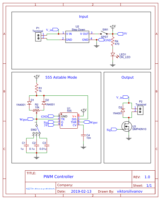
Circuit BoardI used a buck converter to drop the input to 7V for the 555 timer. This helps protect it from supply voltages that exceed the maximum input voltage, per the datasheet.
The poor man's variable capacitor using a 3 position switch and different caps:
The MOSFET steer power to the load. The gate is driven by the 555 timer.
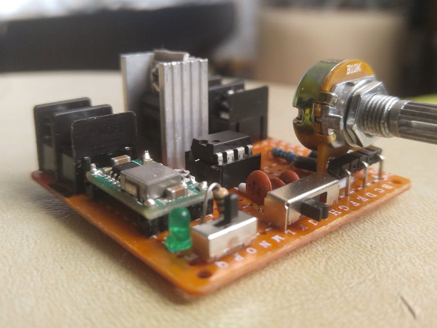
Fully assembled:
Here's another functional example where I drive a fan with the board.


Comments
Please log in or sign up to comment.