


Hardware components | ||||||
_ztBMuBhMHo.jpg?auto=compress%2Cformat&w=48&h=48&fit=fill&bg=ffffff) |
| × | 1 | |||
| × | 1 | ||||
| × | 1 | ||||
In this tutorial we gonna interface the Capacitive Touch buttons module with Arduino Uno board, and as an example we gonna control a RGB LED, control the colors values using different buttons of the module, of course this can be used later to control anything you want.
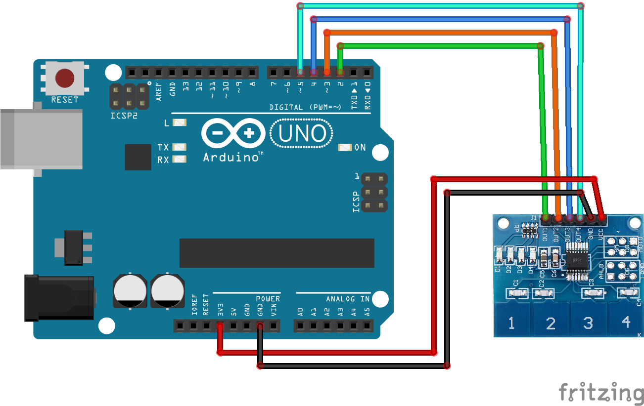
This is the module it has 4 pins for the different outputs, they are digital, and for the power it can be powered by 3.3V or 5V from the Arduino.
The module has 4 built-in LEDs, they light up whenever the respective button is touched, and you can touch multiple at the same time.
The Test 1 is a direct interfacing with Arduino Uno board, and we gonna check the buttons states on the serial monitor.
WiringWiring 1 can be found below.
Any digital pin can be used with the module outputs
CodeCode 1 can be found below.
ResultThe buttons states are displayed as 0/1 on the serial monitor.
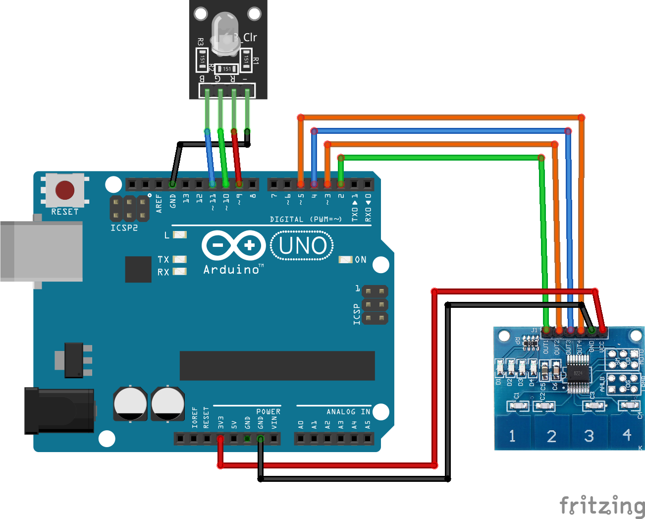
In this test we gonna add a RGB LED, here I’m using a common cathod one.
Wiring 2 can be found below.
Pay attention to the RGB LED it should be wired with PWM pins (~) only and the GND.
CodeCode 2 can be found below.
ResultsThe values (brightness) keeps incrementing until it reaches maximum and resets from 0.
Also the fourth button resets all values to 0.
And of course you can mix the colors
Also if you keep touching the button it will count as multiple touches.
That’s all folks !Don’t forget to subscribe the channel for support.

Comments
Please log in or sign up to comment.