Level: Beginner
Exercises Covered: Blink 1 LED Change Pin on Microcontroller for Output Add LEDs to the Blink LED Program
Theory Lessons: What are Pins (on a Microcontroller)? Parts of an Energia Program-Sketch
Concepts Used: How to Wire Up a Breadboard How to Wire a Breadboard with an LED Using Energia Examples
Concepts to Learn: Wiring more than 1 LED Microcontroller pin out Changing and modifying a program
---------------------------------------------------------------------------------------------------------------Getting Started: Verify your LaunchPad is working. Plug your LaunchPad into the computer.
Wire up your breadboard. Connect 1 of the jumper wires from the side of the breadboard you are using - (blue) to the GND terminal on the LaunchPad. This is providing power to the breadboard.
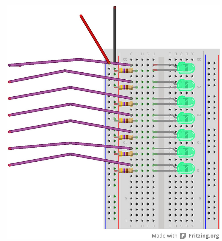
Start with connecting a 560K resistor from the negative column to the row you will be connecting the negative of the LED. (suggest from the Blue (-) rail one end of the resistor and connect the other end of the resistor to row 3 column c).Hold up the LED, there is a long leg and a short leg.
Orient the LED so the short leg is going into row 3 and the long leg is going to row 2- ( suggest plugging into column e).
Then you will connect the jumper wire. This will be your positive. Connect the jumper wire from the positive of the LED (remember we plugged it into row 2, so you will want to plug the jumper into one of the 4 remaining spots on row 2).
Normally you would connect the jumper wire to the pin on the LaunchPad, but in this case we're going to leave that last wiring until later. However, we will use this opportunity to test the LED.
Take the jumper (with the female end) and touch it to the VCC pin of the LaunchPad. You should see the LED light up. Keep it disconnected and move to the next LED.
**For help here, look at this tutorial on how to use a breadboard and wire 1 LED by ScienceOnline below.
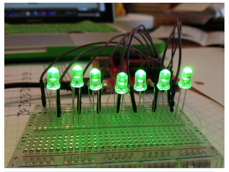
Wire up the rest of the LEDs, testing each one of them as you go along (touching the end of the positive jumper to VCC) and verifying that the LED does work. This is how we wired ours:
------------Exercise1: Blink 1 LED Now that you have the hardware all wired up, you're ready to start to connect the LaunchPad to the wires.
The first step is to open up the Blink LED Example and load and execute the program. - Open Energia
Load the Blink LED Program. This turns on the LED for 1 second then turns it off for one second. - File--> Examples--> Basic--> Blink LED- Hit the LOAD Button
This is to blink only 1 LED.
If you notice it, pin 14 is what is called out. Go through each line of the code and change it to pin 3.
When you are done, hit LOAD.See the LED Turn off.Now that the LED has turned off, this means that your program has loaded. Instead of turning Pin 14 on and off... it is now turning on and off Pin 3. But, you don't have anything connected on Pin 3.So, let's wire something to Pin 3, but first, we need to know what Pins are.THEORY: What are Pins?When you look at your Energia Sketch, you see that it declares a "Pin"The Pin that the sketch is referring to is the "Pin" on the microcontroller. The microcontroller on the LaunchPad is the MSP-EXP430G2, which has 20 Pins. It's useful to learn what your microcontroller's "Pin out" is, which you can usually find in the microcontroller's datasheet.
The one thing you need to pay attention to is where the numbers are on pin-out. These numbers correspond to each of the device's Pin's. This is what Energia is calling out when it says, Pin 14.
Here is the pin map for this LaunchPad provided by the Energia websitehttp://energia.nu/pinmaps/msp-exp430g2/
Luckily the LaunchPad also has 20 pins and it aligns nicely with the pin-out on the MSP430 device.This means that when we refer to Pin 3 on the Microcontroller, you can easily count the header pins to find Pin 3.
The LaunchPad's header pins have a "silkscreen" that labels each of the pins to help make it easier for users. You can use the silk screen to help you remember what each pin does.**You should already have VCC and GND connected to jumper wires to the + bus (red) of the breadboard and the - (blue) bus. This means you have Pins 1 and Pins 20 tied to + and -.
This will be particularly important when:1. You want to take the microcontroller off of the LaunchPad and place it on the breadboard2. You have a microcontroller that may have less pins than what the LaunchPad has.**For now it's important for you to know that the software (Energia) is talking to the microcontroller, but the physical part (the wires and the breadboard) are talking to the LaunchPad. If you want to move a pin, you will need to make sure to make a change in both, the microcontroller and the wires.**
Exercise2A: Continue to change Pin... Connect LED A to Pin3Let's get back to our breadboard.So, we have loaded already a program that is making the LED blink for 1 second on and 1 second off for Pin 3. (You can either count the pins starting from Pin 1 to get to Pin 3, or you can use the silk screen to find P1.1. ) Take the jumper from LED A that isn't connected to anything (the other 6 should still be disconnected since only the + and - buses are connected) and connect it to Pin 3.
The LED A should begin to flash.
Now, we are ready to make the rest of the LEDs blink.The hardware (in this case the breadboard) is already wired up. All we need to do is get the program modified and ready to work and then connect the hardware. So, getting to work on the program first...
------
To be able to modify the microcontroller to have more LEDs we need to change the program or "sketch" to have the extra pins. Let's first understand the parts of a sketch.THEORY: Parts of a "Sketch"(Energia Program)Go back to the Energia Window and look at how the program is put together.
In general you will declare variables- although this program doesn't have any yet. Then you need to initialize the pins that are getting used (tell the program what microcontroller pins it should be paying attention to). Then it runs the program.So, looking at the Blink LED Program (above) we can read it to be: There are no variables. Set up pin 3 (connected to LED A) to be an output. When the program runs, it will do a digitalWrite of pin 3 to be HIGH or "on" delay for 1000 mili seconds. (keep it on high for 1 second). Then do a digitalWrite of the same pin (pin3) to be LOW or "off" and delay for 1000 milliseconds. then it repeats (the loop).and modify the program to basically add another LED. we'll need to Set Up that pin. Then add it to the program.
Exercise: Add LEDs to the Blink LED Program.Modify your program to look like this:
Hook up LED B cable to Pin 4. Now you should have LED A blink for one second, then turn off. Then LED B blinks for one second then turns off.
Continue to add the rest of the pins. If you wanted to only to have each LED blink for 1 second in sequence you can use this method. Make sure to connect your LEDs to the board to the corresponding pins.Example Code is attached to the end of this post.You can either open that code and copy and paste it over your existing program or you can choose to type it out.
Once you have the new program loaded and the LEDs wired to the correct pins you should have all seven LEDs blinking one at a time and repeating.
Congratulations, you've blinked all seven LEDs! You can stop here and play with the delay times, change the order of the blocks of code (if you put the code in different orders, you'll get different routines) - the options are endless! Happy engineering!


_3u05Tpwasz.png?auto=compress%2Cformat&w=40&h=40&fit=fillmax&bg=fff&dpr=2)

Comments
Please log in or sign up to comment.