Most of my fishing is trolling for trout on a deep water reservoir. Trout can be very finicky as to lure speed. One day they prefer 1.5 mph. The next they want 2.1 mph. My outboard trolling motor on my boat has a typical twist hand throttle with a twist lock. It is very difficult to dial in an exact speed because of the lack of sensitivity of the twist hand throttle.
Most books recommend you troll in a S-curve pattern. That way the lures on the outside of the turn speed up and on the inside of the turn slow down. This promotes reaction strikes by the fish. They think their prey is either trying to get away or is now wounded and fluttering. However trolling all day in an S-pattern is a pain. You can also duplicate the lure speeding up or slowing down with the throttle. However it is very difficult to do correctly by hand and also tiring. It is not that difficult to do with an Arduino controlling a servo that controls the throttle.
There are a few mannufacturers that sell expensive throttle controllers. Instead of buying one, I thought this would be a great first project to learn the Arduino.
Step 1: Determine How to Mount Your ServoDifferent motor manufacturers will require different solutions on how to mount the servo and control the throttle linkage. The first photo shows my motor as it comes from the factory. Note the original stainless steel throttle linkage. The second photo shows the finished servo mount and new fabricated throttle linkage that was required to make this work with my Honda outboard. I fabricated the servo mount and the new throttle linkage out of stainless steel. The cable and crimps are 45 lb test steel fishing leader purchased from Cabelas. I used a HS-475HB servo purchased from ServoCity. Regarding the cable connecting the servo horn to the throttle linkage. A cable is used so that the twist throttle still works in case you have a malfunction or don't want to use the throttle controller. Don't use a solid connector like a Z-rod.
A search for the installation manuals provided by the various throttle controller manufacturers will provide some ideas on how they control throttles on various brand motors if you can't figure it out on your own.
Step 2: Prototype Your Circuit and Write Your CodeTrolling for fish requires the ability to accurately dial in the exact speed the fish prefer that day. In addition, many fish strike due to a reaction when a lure speeds up or slows down. I programmed this speed controller to implement these requirements.
My throttle controller has the following features:
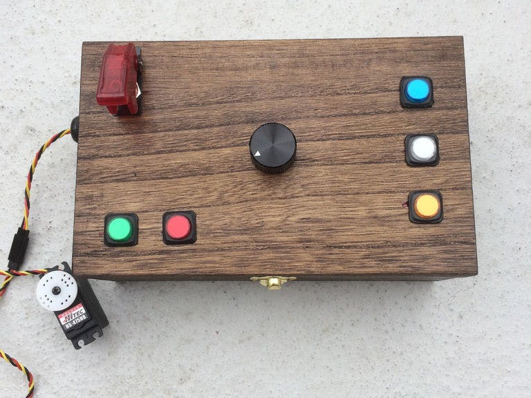
- A central dial that turns a potentiometer that controls the position of the servo. I can now dial in my speed to the 1/10th mile per hour.
- A green button that when pushed and held down runs the motor at full throttle. When the button is released, the motor returns to the speed on the dial. This is to quickly gain control of the boat in a gust of wind, current, to avoid an obstacle, etc.
- A red button that when pushed, runs the motor at idle speed. When pushed again, it returns to the speed on the dial. This is for when fighting a fish. You still need some forward speed to keep control of the boat, especially in the wind.
- A blue button that when pushed, runs the motor at the speed on the dial for 45 seconds and then speeds up for 10 seconds, then returns to the speed on the dial for 45 seconds. It keeps repeating until the blue button is pushed a second time. This simulates trolling in S-curves and triggers reaction strikes.
- A white button that when pushed increments the speed every 60 seconds three times and then decrements the speed every 60 seconds three times returning to the original speed. It keeps repeating until the white button is pushed a second time. This makes it easier to determine what speed the fish prefer that day.
- A yellow button that when pushed, runs the motor at the speed on the dial for 45 seconds and then decreases speed for 10 seconds, then returns to the speed on the dial for 45 seconds. It keeps repeating until the yellow button is pushed a second time.This simulates trolling in S-curves and triggers reaction strikes.
The source code is available at: Trolling_Motor_Code
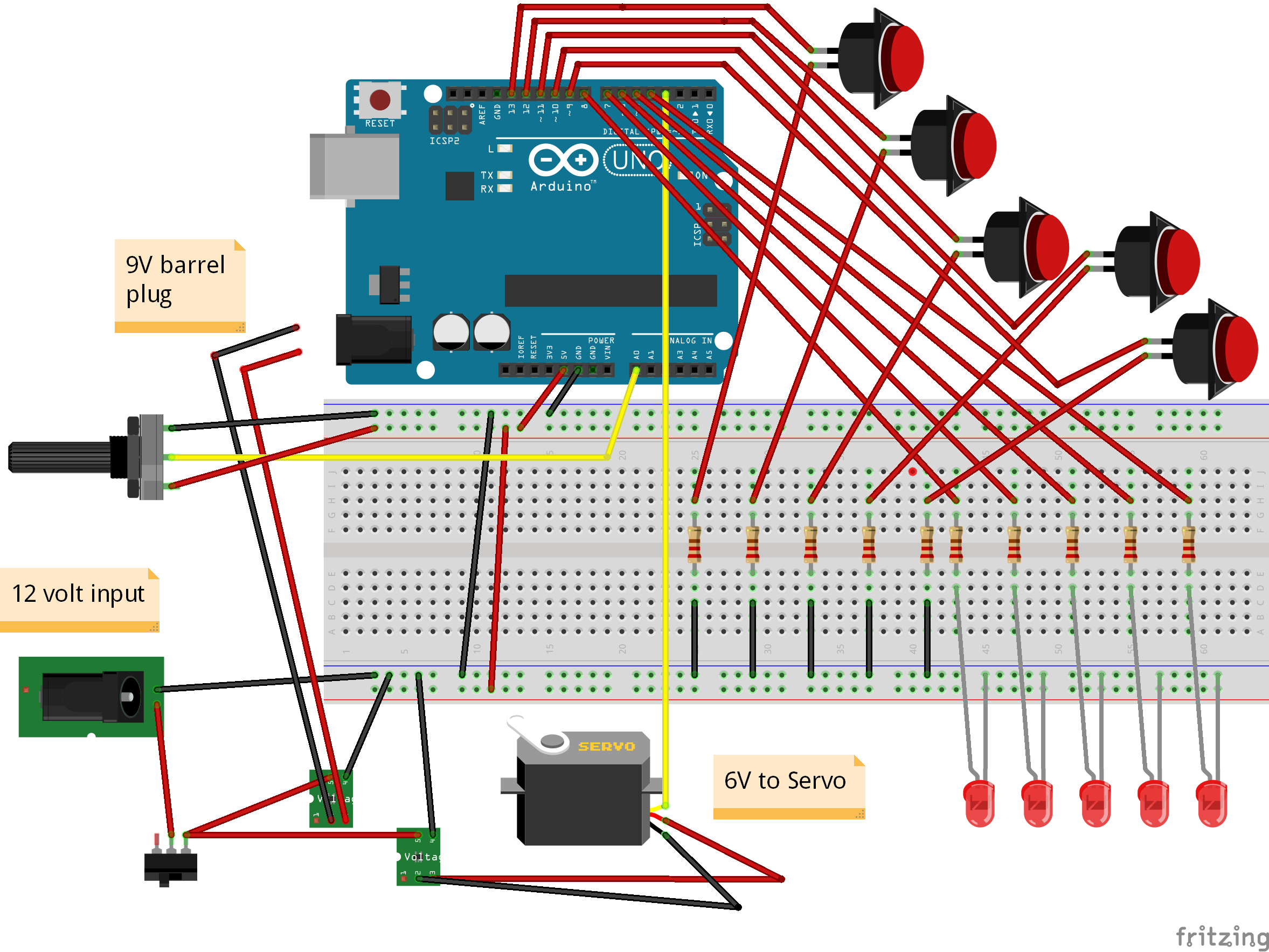
Step 3: Put Together the ElectronicsHere's a photo the start of the electronics showing the power switch, two voltage regulators and the push buttons. The input power is 12 volts and comes from the cigarette lighter on the boat. The two voltage regulators provide 6 volts for the servo (it is a long way to the back of the boat) and 9 volts to the Arduino. The project box came from a hobby store and was under $10.00. A little stain and it came out pretty good.
Step 4: Test the ControllerThe video is pretty rough, but you can listen to the pitch of the outboard motor as the dial is turned or the full throttle and idle speed buttons are pushed. Depending on your outboard, you may have to adjust some of the servo settings in the source code to get the speeds you want. Overall this was a great first Arduino project.


_ztBMuBhMHo.jpg?auto=compress%2Cformat&w=48&h=48&fit=fill&bg=ffffff)


Comments
Please log in or sign up to comment.