Hey techies, do you know the working of a water level depth detection module? In this article, we are going to teach you how you can make a water level indicator using NodeMCU. This sensor is used to find the level of the water raised into the container. This technology can be used to tell that the water tank is full or not. You can read the full article on our website.
How Does Water Level Indicator Work?While working with this module please place it vertically inside the container. When the output value of the water level sensor is above then 400 the red LED will glow, for the output value above then 540 the green and red LED will glow, and for the output value above then 580 all three LEDs will glow. But if you are using an RGB LED module one LED will glow at a time.
- NodeMCU esp8266 board
- Water level sensor
- Jumper wires
- Breadboard
- USB cable for uploading the code
- Three 220-ohm resistors
- LEDs of red, yellow, and green color or KY-016 RGB LED module
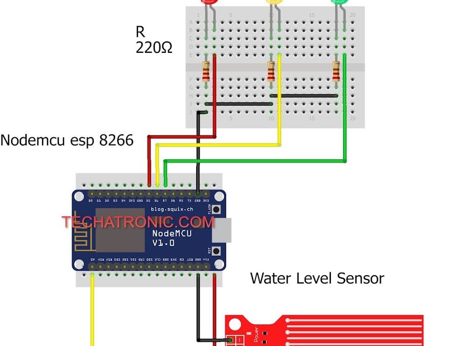
You have to make the circuit according to the given diagram. Connect the VCC pin of the water level sensor with the Vin pin of the NodeMCU. Attach the GND pin of the water level sensor with the GND pin of the NodeMCU. Join the signal pin of the water level sensor with the analog-0 pin of the NodeMCU. If you are using the RGB LED module, connect the GND pin of the module with the GND pin of the NodeMCU. Join the R pin of the module with the digital-7 pin of the NodeMCU. Attach the G pin of the module with the digital-6 pin of the NodeMCU. Connect the B pin of the module with the digital-5 pin of the NodeMCU. If you are using separate LEDs then connect the negative leg of all the three LEDs with the GND pin of the NodeMCU through a 220-ohm resistance and the positive with digital-5, 6, 7 as shown above.
Water Level Indicator NodeMCU CircuitNOTE: Please upload the code given below to the nodemcu.
- Use this code if you are using separate LEDs
// TECHATRONIC.COM
int val = 0 ;
void setup()
{
Serial.begin(9600); // sensor buart rate
pinMode(14,HIGH);  // Red led Pin Connected To D5 Pin
pinMode(13,HIGH);  // Green Led Pin Connected To D7 Pin
pinMode(12,HIGH);  // Yellow Led Connected To D6 Pin
}
void loop()
{
int s1=analogRead(A0); // Water Level Sensor output pin connected A0
Serial.println(s1);  // See the Value In Serial Monitor
delay(100);      // for timer
if(s1> 400 )
{
digitalWrite(14,HIGH);   // Red led ON
}
else
{
digitalWrite(14,LOW);    // Red led OFF
}
if(s1>540 )
{
digitalWrite(12,HIGH);   // Green led ON
}
else
{
digitalWrite(12,LOW);   // Green led OFF
}
if(s1>580 )
{
digitalWrite(13,HIGH);  // Yellow led ON
}
else
{
digitalWrite(13,LOW);  // Yellow led OFF
}
}- Use this code if you are using a KY-016 RGB LED module
// TECHATRONIC.COM
int val = 0 ;
void setup()
{
Serial.begin(9600); // sensor buart rate
pinMode(14,HIGH);  // Blue led Pin Connected To D5 Pin
pinMode(13,HIGH);  // Red Led Pin Connected To D7 Pin
pinMode(12,HIGH);  // Green Led Connected To D6 Pin
}
void loop()
{
int s1=analogRead(A0); // Water Level Sensor output pin connected A0
Serial.println(s1);  // See the Value In Serial Monitor
delay(100);      // for timer
if(s1>400 && s1<500 )
{
digitalWrite(14,HIGH);   // Blue led ON
}
else
{
digitalWrite(14,LOW);    // Blue led OFF
}
if(s1>500 && s1<550 )
{
digitalWrite(12,HIGH);   // Green led ON
}
else
{
digitalWrite(12,LOW);   // Green led OFF
}
if(s1>550 )
{
digitalWrite(13,HIGH);  // Red led ON
}
else
{
digitalWrite(13,LOW);   // Red led OFF
}
}
Also, do check out the latest tutorials on Arduino and Raspberry Pi written by us.
HAPPY LEARNING!


_ztBMuBhMHo.jpg?auto=compress%2Cformat&w=48&h=48&fit=fill&bg=ffffff)


_3u05Tpwasz.png?auto=compress%2Cformat&w=40&h=40&fit=fillmax&bg=fff&dpr=2)
Comments
Please log in or sign up to comment.