


Required Components:
Arduino (Atmega8),
ADXL335 Accelerometer,
HCSR04 Ultrasonic Module and 16x2 LCD
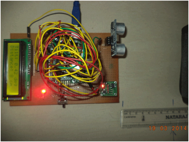
This project demonstrates the interfacing of Accelerometer (ADXL335) with Arduino and calibrating it to measure Angle from a reference plane. Also measuring the distance from object in its line of sight.
The sensor data is fed to Arduino (Analog Input), it is processed and then the values are displayed on and 16x2 LCD.
ADXL335
ADXL335 is 3-axis accelerometer with analog output from Analog Devices. ADXL335 acceleration measurement range is +/- 3 g.
The Voltage requirement of IC-ADXL335 is typically 3.3V, but the module has on board regulator, which facilitates connection of 5V supply to it. It is extremely Low-Power device.
The module has 5 Pins, VCC(5V); GND; and X, Y, Z. The pins X, Y, Z give the acceleration in terms of Voltage, with a typical sensitivity of 300mV. The Analog signal on these pins is Digitized using ADC of Arduino, and required calibration is done through Software.
HCSR04 Ultrasonic Sensor Module:
The sensor module has 4-pins out of which Pin-1 and Pin-4 are +Vcc and Gnd respectively.
Pin-2 is Trigger and Pin-3 is Echo pin.
The working of sensors can be described from the below figure :
When a High pulse of 10us is applied at TRIG pin, the ultrasonic transmitter sends 8 consecutive pulses of 40kHz frequency.
As the Eighth pulse is sent the ECHO pin of the sensor becomes HIGH.
Now when the ultrasonic waves reflect from any surface and are received by the Receiver, the ECHO pin becomes LOW.
The time it takes to leave and return to sensor is used to find the distance from the reflecting surface.
Distance in centimetres = (Time/58) cms
16x2 LCD:
16x2 alphanumeric LCD can display 16 characters in each of its row, and it has two rows. To interface an LCD we need to know about its internal registers and pin functions.
An LCD has two important registers namely command register and Data register. Both are 8-bit registers. The command register is written with various commands by the user. These commands are responsible for the functioning of LCD.
The data register is loaded with the ASCII value of the Data (Character/Number, etc.) to be displayed.
Both the registers are accessed through 8-bit Data Line (D0-D7). There is one selection line provided, namely R/S Pin, in LCD Module which selects between these two registers.
R/S=0à Command Register
R/S=1à Data Register
Apart from R/S, there are other two Pins, viz. R/W and EN.
EN pin is to enable (1) or to disable (0) the LCD.
R/W is used to select the operation ‘Read from LCD’ or ‘Write to LCD’. Logic 0 at R/W stands for Write operation and 1 for Read operation.
Apart from these pins, the last two Pins (15 & 16) on the LCD are for Backlight. And pins 1, 2, 3 are for GND, +VCC and +VEE(contrast adjustment) respectively.
There are various commands that need to be send to LCD so as to Initialize it, to make it work accordingly. These command are listed below.
The sensor output at different positions (as shown in picture) helps to find the sensitivity and ADC reference values. In Position 1 in picture, the X-pin gives voltage that corresponds to -1g; Y and Z correspond to 0g. Similarly, for all other positions the values of X, Y and Z give corresponding analog voltage.
These Analog Voltage values are fed at Analog Input Pins of Arduino (say A1, A2, A3). The ADC is 8-bit and has 10 bit resolution.
Voltage difference (range) between +1G and -1G divided by 2 would be the sensitivity (‘sensitivity_x’ in below formula). And the Voltage corresponding to 0g gives ‘Zero’ Voltage (zero_x in below formula). The ‘Zero’ value and sensitivity differs depending on the sensor and thus have to be found by trial and error.
The ADC reference is 3.3V (Externally provided from the board). The formula for calculating the acceleration in ‘x’ axis would be:
Xg=(value_x/1024) * (ADC_ref – zero_x) / (sensitivity_x)
Similarly, Yg can be calculated using values of value_y; sensitivity_y and zero_y for ‘Y’. Do the same for Zg.
NOTE: If a direction of sensing axis match to gravity direction measurement result is negative (-1 g).
Measurement of Tilt/Slope/AngleTo calculate the Tilt/angle from HORIZONTAL plane (XY Plane), we make use of ‘arctangent’ or ‘atan2’ function.
The function atan2 is the arctangent function with two arguments. The purpose of using two arguments instead of one is to gather information on the signs of the inputs in order to return the appropriate quadrant of the computed angle, which is not possible for the single-argument arctangent function.
For any real number (e.g., floating point) arguments x and y not both equal to zero, atan2(y,x) is the angle in radians between the positive x-axis of a plane and the point given by the coordinates (x, y) on it. (wikipedia)
Here, we need to calculate the angle from XY Plane, horizontal is y-axis and the vertical is z-axis. So, the Formula becomes:
angle = atan2(-yg, -zg);
Since the value is in radians, it is converted to degrees by multiplying with 180/?, which is 57.295.
Also 180° is added to adjust the initial value. The formula now becomes:
angle =atan2(-yg, -zg)*57.2957795+180;
The Value obtained is then displayed on 16x2 LCD Display.
To facilitate the User Interface, a switch is interfaced to provide a control on LCD, to choose what to display on screen. Say, when switch is ONàAcceleration value is displayed; and when switch is OFFàAngle/Tilt and Distance is displayed.
LCD is interfaced in 4-bit mode, by using the predefined library of Arduino.
Make Connections as below:
· X, Y and Z pins of Accelerometer to Analog Input Pins 1, 2 and 3 respectively.
· ‘AREF’ is connected to 5V.
· D4, D5, D6 and D7 pins of LCD are connected to Digital Pins 5, 4, 3 and 2 of Arduino.
· RS and EN pins are connected to Pin 12 and Pin 11 of Arduino.
· RW pin of LCD is connected to GND.
Switch is connected to Digital Pin 1 and a current limiting resistor (10k) is also connected to it.
NOTE
Set the values of Sensitivity and Zero, according to the sensor output measured by multimeter, etc. Because the value used here may vary for various sensors.
ADC_ref could be changed to 3.3V also, but then do change ‘Zero’ values accordingly.
Angles from various planes can also be calculated. For calculating angle from x-axis when y is vertical, the formula would be:
angle= atan2(-yg, -xg)*57.2957795+180 //angle from x-axis
Similarly angle from y-axis can also be calculated.

Comments
Please log in or sign up to comment.