In today’s greenhouses, many parameter measurements are required to monitor and control for the good quality and productivity of plants. But to get the desired results there are some very important factors which come into play like Temperature, Humidity, Light and Water, which are necessary for a better plant growth. Keeping these parameters in mind I have built an automatic greenhouse controlling and monitoring system over GSM module using Arduino. This system is very efficient for growing good quality plants. The other important part of this project is that it is fully automatic. Arduino automatically turns on and turns off the appliances.
These days GSM module is widely used in greenhouse monitoring. Here in this project by using GSM module we can keep information about the effects of climate on plants. The system shall also demonstrate climatic changes which affect the plant in its productivity and quality etc. The main purpose of coming up with this project is to build an automatic greenhouse monitoring in which GSM module sends the information about temperature, humidity, light intensity, soil moisture and status of appliances (fans, sprays, artificial lights and water pump) that are connected with circuit for controlling greenhouse effects or greenhouse parameters (temperature, humidity, light intensity and water supply for plants).
Block Diagram of Greenhouse Monitoring and Controlling System
The four parameters that we are going to discuss are:
Temperature
The temperature sensor is used for sensing temperature. When temperature exceeds from a defined level or critical level, the system automatically turns on the fan and a message is also sent to the owner or the operator with information of all parameters (Temperature, Humidity, Light intensity and Electrical appliance on off status). And when the temperature comes in normal range or comes below the defined level the fan turns off automatically.
Humidity
Humidity is measured by using the humidity sensor. If the humidity of the environment is below the defined levels, sprays are automatically turned on and if the humidity level exceeds from the defined level sprays are automatically turned off. But here in this project instead of a spray I have used CFL light to denote the spray. A status or notification message is also sent to the owner by the system using GSM Module.
Light Intensity
Light intensity is an important factor for the plant growth. If the light intensity is low then it affects the growth of the plants. To resolve the problem of low light, artificial lights are used. Here in this project 100 watt bulb is used for demonstration. When light intensity is lower than a defined level, the artificial lights turns on, and when the light intensity comes in normal range artificial lights automatically turns off and a notification message is also sent to the owner.
Light Intensity Sensor Circuit Diagram
For detecting light intensity LDR is used. Generally light intensity is measured in LUX and therefore for demonstration 100 LUX light is used as defined or threshold level. If light intensity exceeds from 100 LUX, the artificial lights automatically turns on.
For more detail about light intensity circuit and measurements, please read “Solar Power Measurement System using Arduino”.
Soil Moisture
Water supply for plants is very important for good growth. So here in this demonstration I have used a water pump and a soil moisture sensor, for detecting soil moisture. Two probes of soil-moisture-sensors are used and placed in soil. When the sensor does not sense moisture in soil then the system turns on the water pump until it reaches the required level. A notification is also sent to the owner with status of water pump like Motor On or Motor Off. Here for sensing soil moisture a transistor is used as a switch.
Circuit Description & ProgrammingCircuit Description
In this system Arduino is the heart of whole system which takes control over the process. When sensors sense any change in environment or in soil Arduino comes in action and process the required operation.
When soil moisture sensor does not sense moisture in soil then Arduino turns on the water pump and sends a message to the owner of status that the motor is turned on.
And if LDR senses low light then Arduino takes control and turns on the artificial lights.
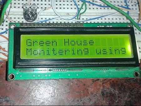
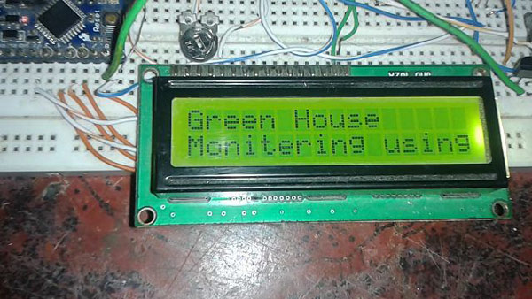
In this system a 16x2 LCD is used for displaying status for all operations like Motor turned on or off, temperature, humidity and light status. The LCD’s data pins are connected in 4-bit mode (data pin d5, d6, d7, d8 pin of LCD is directly connected with pin no. 4, 5, 6, 7 of Arduino and command pin of LCD’s Rs and En is connected with pin no. 2, 3 of Arduino). LDR is used for sensing light intensity and its output is connected to Analog pin A0 of Arduino while the artificial light is connected using relay. The relay is operated by using ULN2003 and controlled using pin number 10 of arduino. Humidity and temperature sensors are used for sensing humidity and temperature that are connected directly with Analog pin A1 of Arduino. Fan is directly connected with pin 8 of Arduino and CFL light (in place of Sprays) is connected with pin 11 of arduino by using Relay. Water pump is also connected by using relay and is controlled by Arduino’s pin number 12 and the sensor for measuring the soil moisture, pin number 9 is used.
GSM module is also connected with this circuit for sensing message alert of the status to be sent to the owner. GSM module’s Rx pin is directly connected with Tx pin of Arduino. For detailed information of sending message using GSM please have a look on our previous projects related to Sending Messages using GSM module and Arduino.
Programming
Programming part of this project is very easy. In this program DHT library is used for reading the Humidity and Temperature from the humidity and temperature sensor (DHT11 basic), which is displayed on LCD and sent to the owner by using GSM module. Here for sending message, 9600 baud rate is used by using class “Serial.begin(9600)”.
Circuit Diagram
For circuit kindly refer to the circuit diagram tab of Greenhouse Monitoring and Controlling System.
Components Used
1. Arduino Pro Mini
2. GSM Module
3. 16x2 LCD
4. Humidity and Temperature (DHT 11 basic)
5. LDR
6. Bulb
7. CFL light in place of spray
8. Relay 5 volt
9. ULN 2003
10. BC 547
11. 50 k POT
12. 1 k resistor
13. Bread Board
14. Connecting Wire
15. Power Supply
.


Comments
Please log in or sign up to comment.