Description
The mouse and the Keyboard form the standard input unit for a Personal computer. The QWERT keyboard which is used in the PC comes with a PS2 connector or USB port connector. The PS2 keyboard uses a simple synchronous serial protocol using only two wires for communication. Due to its simplicity the PS2 keyboards are widely used with simple microcontroller based boards also. The PS2 keyboard always acts as a slave device which can send the equivalent ASCII value of the key which has been pressed to its master device which can be a PC or a microcontroller.
The ZigBee is the name of a wireless protocol maintained by the IEEE 802.15 standard. This is a protocol specified for wireless Personal Area Network (PAN) using low powered wireless transceivers. There are already wireless transmitter and receiver modules which can do point to point communication. The Xbee is the brand name a wireless transceiver device which works on the ZigBee protocol and can form PAN networks.
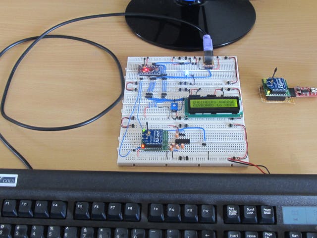
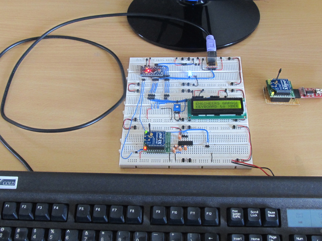
Xbee modules have an approximate range of 100 meters and are used in industries, scientific fields, medical fields etc. The Xbee module even though uses complex packet data based Zigbee protocol for communicating with each other, they can communicate with other devices using simplest serial communication protocol and hence they are widely used in microcontroller base boards. This particular project demonstrates how to transmit the data from a PS2 keyboard to a remote computer using Xbee transceivers.
Any AVR microcontroller based board which follows the standard Arduino schematic and is flashed with the Arduino bootloader can be called an arduino board. The arduino boot-loaderenables different Arduino boards to be connected and programmed with the Arduino IDE. The Arduino board used in this project is the Arduino pro-mini board and the IDE version of the arduino is 1.0.3 for windows.
The image of the Arduino pro-mini board and the Arduino IDE are shown below:
Fig. 2: Typical Arduino Pro-Mini Board
Fig. 3: Arduino IDE Software Window
Since the Arduino pro-mini board has no circuitary for interfacing it with the serial port or the USB port of the PC, an external USB to TTL converter board is required to connect it with the PC. This hardware helps in programming the Arduino board and also helps in the serial communication with the USB port of the PC.
Fig. 4: External USB to TTL converter board for programming Arduino and serial communication
It is assumed that the reader has gone through the project how to get started with the Arduino and tried out all the things discussed there. The image of the Xbee S1 series module used in this project is shown in the following image. Since the pitch of the pins of the modules are not breadboard compatible one can use the Xbee based design boards which comes with breadboard compatible pins.
Fig. 5: Xbee S1 Series Module
Since the Xbee modules communicate using serial communication protocol with the interfacing devices they can be connected to a microcontroller using a minimum of four pins, Power supply, and Ground, UART Data Out, and UART Data In pins. The Xbee modules have several digital and analog I/O pins apart from these pins and the pin out of an Xbee module is shown in the following table:
PIN
DESCRIPTION
1
Power Supply
2
UART Data Out
3
UART Data In
4
Digital Output 8 (not supported as of 2/28/09)
5
Module Reset (reset pulse must be at least 200 ns)
6
PWM Output 0 / RX Signal Strength Indicator
7
PWM Output 1
8
Do not connect
9
DTR / Pin Sleep Control Line or Digital Input 8
10
Ground
11
Analog Input 4 or Digital I/O 4
12
Clear-to-Send Flow Control or Digital I/O 7
13
Module Status Indicator
14
Voltage Reference for A/D Inputs
15
Associated Indicator, Analog Input 5 or Digital I/O 5
16
Request-to-Send Flow Control, Analog Input 6 or Digital I/O 6
17
Analog Input 3 or Digital I/O 3
18
Analog Input 2 or Digital I/O 2
19
Analog Input 1 or Digital I/O 1
20
Analog Input 0 or Digital I/O 0
Fig. 6: Pin Out of Xbee module
Since the Xbee modules communicate using serial communication protocol with the interfacing devices they can be connected to a microcontroller using a minimum of four pins, Power supply, and Ground, UART Data Out, and UART Data In pins.The pin number 2, UART Data Out is connected to the RX1 pin of the Arduino pro mini board and pin number 3 UART Data In is connected to the TX0 pin.
The keyboard always has 6 pin mini-DIN male connector for PS2 interface and the host device always has the corresponding female pin. The images and the pin-outs of the PS2 male and female connectors are shown in the following image, the only difference between the PS2 keyboard and mouse connectors are in their color.
The image of the PS2 male pin
Fig. 7: 6 Pin Mini-DIN Male Connector For PS2 Interface
The image of the PS2 female pin
Fig. 8: 6 Pin Mini DIN Female Connector Plug for PS2 interface
The pin-out of the PS2 male and female connectors
Fig. 9: Pin-Out Of PS2 Male Connector and Pin-Out Of PS2Female Connectors
When it comes to connecting the female connector with the circuit board one should be able to identify the pins at the bottom of the PS2 connector and the following image will be helpful.
Fig. 10: Bottom of Mini DIN Female Connector Plug for PS2 interface
The implementation of the project which can receive the data from the PS2 keyboard and transmit the characters one typed on the keyboard to a remote computer through Xbee is represented using the following block diagram:
Fig. 11: Block Diagram Of Data Transmission bewteen Keyboard and Computer Using Xbee
The code written for this project reads the data from the PS2 keyboard using the custom PS2 library file called “PS2Keyboard.h” which has all the necessary routines for accessing a PS2 keyboard. The details of how to use this library to interface a PS2 keyboard is already discussed in a previous project on how to interface the PS2 keyboard with the Arduino. There are basically three functions which the user can directly make use in their code and are namely “keyboard.begin()”, keyboard.available() and “keyboard.read()”. The details of the functions are discussed in the following.
keyboard.begin()
The function keyboard.begin() is used to perform all the necessary things to initialize an ASCII keyboard using PS2 protocol. Once the initialization is done properly each time a key is pressed the keyboard starts sending the equivalent ASCII value of the key which has been pressed. The function takes one parameter and it is the number of the pin in the Arduino board which acts as the Data pin of the keyboard.
keyboard.available()
This function can be used to check if a data regarding a key press is available from the keyboard. This function is always called before calling the keyboard.read() function which is used to read the data from the keyboard. The function returns a non-zero positive value whenever a key press is detected.
keyboard.read()
The function keyboard.read() can be used to read the ASCII value of a key which has been pressed from the keyboard. The function does not take any parameter and it returns the ASCII value of the key. The function keyboard.read() is always called after the function keyboard.read() returns a non-zero positive value.
The Arduino board writes the PS2 keyboard data to the Xbee for transmission with the help of serial communication functions provided by the Arduino library. The functions like Serial.begin() which helps to initialize the serial port with a given baud rate, Serial.write() to send a data to the serial port, Serial.available() and Serial.read() functions to read data from the serial port are used in this project and they are already discussed in previous projects on how to do serial communication with the Arduino, how to send and receive serial data using arduino and how to do serial debugging with the Arduino. The method of interfacing a Xbee module and transmission of data using it is discussed in as previous project on how to interface Xbee module with Arduino.
When the coding is finished one can verify and upload the code to the Arduino board as explained in the project how to get started with the Arduino. As soon as the board is powered up the Xbee in the Arduino board automatically establishes communication with another Xbee which is connected to the serial port of a PC. The second Xbee board can be connected to the PC using the same USB to TTL converter board which has been used to program the Arduino board. The letters typed on the PS2 keyboard will get transmitted and can be read on the PC using any serial monitoring software or using the Arduino IDE’s serial monitoring software itself as explained in the project how to do serial debugging with the Arduino.
Components
- 109, 275-Reads
The Arduino Pro Mini is an ATmega168 based microcontroller board. The board comes with built-in arduino bootloader. It has 14 digital input/output pins (of which 6 can be used as PWM...
- 66, 918-Reads
Light emitting diodes
...
- 48, 878-Reads
Resistor is a passive component used to control current in a circuit. Its resistance is given by the ratio of voltage applied across its terminals to the current passing through it. Thus a particular value of resistor, for fixed voltage, limits the current through it. They are omnipresent in...
- 39, 876-Reads
Potentiometer (Pot) is another class of variable resistors and is used as an adjustable voltage divider. It consists of a fixed resistance track having connections at both ends and a sliding contact, called wiper, which moves along this track by turning the spindle. If only one of the connections and wiper are used, it behaves as...
- 23479 reads


Comments
Please log in or sign up to comment.