


In present times increasing Traffic is adding to the big woes of developing cities. The main roads are packed with vehicular traffic on each and every road or a traffic signal (Intersection Points). One comes across the common problem of traffic jams on almost all Traffic Junctions which is even critical if you go to big cities. A lot of time, energies besides precious fuel is wasted just because of these Traffic Jams on the roads.
To solve this problem Traffic Cameras are used over Traffic Intersection points. Traffic Cameras capture the image of vehicles in traffic and sends to MATLAB. Here in this project Traffic Surveillance System is demonstrated by way of how the traffic could be controlled over traffic intersection points from the Traffic Control Room. This is a very effective system for Traffic Surveillance.
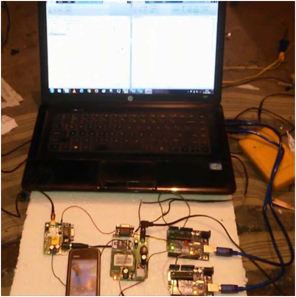
Given below are some snapshots depicting the working of the arduino based traffic surveillance system.
Description
Working of this Traffic Surveillance System is easy and quite simple. There are two Arduino UNO boards which are used for controlling all the operations. GPS and GSM technologies are also used in the project. Here GPS is used for taking coordinates of a Traffic Jam and GSM is used for sending these coordinates to Traffic Control Room. But besides GPS and GSM there are two more other important things which are used in the Traffic Surveillance Project and that are Cameras and MATLAB.
Block Diagram without LCD
MATLAB sends command to cameras for capturing the images of traffic, where MATLAB later identifies or count the total number of vehicles over the Traffic Intersection or over on road. If the total number of vehicles over the road exceeds the limits in a given situation then the MATLAB sends signals to Arduino UNO (A).
Arduino UNO (A) sends interrupt to second Arduino UNO (B). Now the second Arduino UNO (B) takes coordinates of the Traffic Jam and sends these coordinates to the Traffic Control Room using GSM module. Here you can use a LCD for showing the traffic status like Traffic Jam or No Traffic.
Block Diagram with LCD
Circuit Diagram & Programming ExplanationCircuit Description
Circuitry of this system is also quite simple. You can connect the whole system using jumper wire. Laptop Camera is used as Traffic Camera for monitoring purposes and Match Boxes are used in place of vehicles. MATLAB is also used in Laptop for processing the operation of the project. Arduino is directly connected to the Laptop using USB. Arduino UNO’s (A) pin number 8 is directly connected to 8 number pin of Arduino UNO (B). A GPS and a GSM module are connected with Arduino UNO (B). One can also connect a 16x2 Liquid Crystal Display (LCD) with Arduino UNO (B) for displaying Traffic Status.
Please Refer Circuit Diagram Tab for Without LCD and With LCD
Program
There are three programs for this system, first is Arduino MATLAB program for Image Processing and counting the vehicles. Arduino MATLAB support package file should be installed in your computer (see previous article of GUI interfacing with Arduino). Second program is also Arduino MATLAB support package (see previous article of GUI interfacing with Arduino) for Arduino UNO (A). Third program is for Arduino UNO (B) which takes control on GPS, GSM and LCD.
Arduino Program
MATLAB Program
Components Used
1. Two Arduino UNO Board
2. GSM Module
3. GPS Module
4. Laptop
5. 16X2 Liquid Crystal Display(Optional)
6. Power Supply
7. Connecting Wires
.

Comments