UPDATE: I have started this project again. You can learn more on my build log at: https://TheGreatMojaveRover.com
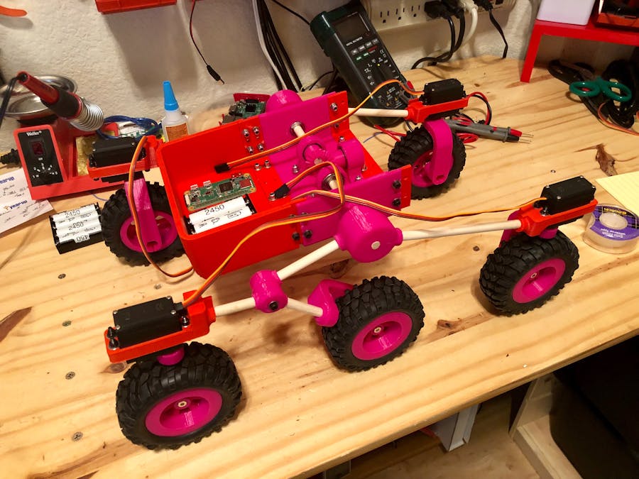
The Great Mojave Rover Project is an autonomous rover built to survive the extreme conditions of the Mojave Desert. The rover will utilize GPS, environmental sensors, remote communication, and cameras for creating a 3D terrain of the explored area, as well as 360º photos. Using a Raspberry Pi Zero and microcontrollers the rover will be controlled remotely over the internet via a web interface powered by a Raspberry Pi 3B+ base station (Mission Control).
The rover will be instructed to travel to a GPS location. The Rover would then figure out how to get there using obstacle avoidance. It would also stop along the way to create a series of photos of the surrounding area. These photos would be either compiled on board or transmitted to Mission Control for processing.
Instructions for the rover will be stored on the server until retrieved by the rover. If no instructions are given, it will wait and try again later in the day. Future versions may start exploring on its own. The rover will also receive over the air updates from time to time.
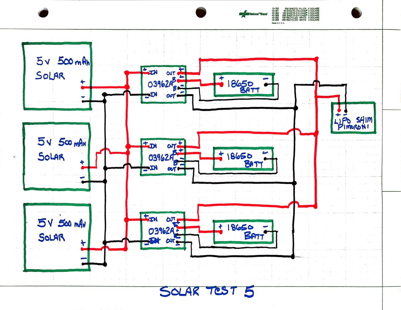
Power for the rover is (8) 2.5-watt 5 volt solar panels charging two sets of (4) 18650 batteries. One set of cells for the compute module, the other for propulsion. The current plan is to keep each set of cells separate. I don't want propulsion to consume all the power for compute. I am also going to put another (2) 18650 batteries for the LTE hotspot.
Mission Goals:- Survive unattended in the desert, for weeks at a time.
- Create a 3D map of the terrain using photogrammetry.
- Explore the desert with no user input other than the destination.
- Send back photos and sensor data.
- Learn how to improve rover.
- Have fun.
The Rover is primarily 3D-printed in PETG. The suspension parts will be 8mm carbon fiber tubes. The camera mast will be a collapsible design that will raise and lower as needed.
I am designing this Rover is designed with help from the internet. The plan is to build two identical rovers. One for the mission the other for the sandbox. All development, testing, and software upgrades will be done in the sandbox first, then transmitted to the deployed rover. I am trying to reproduce the success JPL is having with their rovers.
I will also design the software for driving. The idea is to learn as I go, combining what I come up with, with the best ideas from the internet. I don't want a off-the shelf project. I am looking at making this mine, and sharing it with the world. I would love to see more of the out there.
Video of first prototype running under it's own power, forward and backwards. Note: Steering was not setup at this point. I did do a test with steering, but stupid me I did not record it.
- Solar and battery to supply enough power for 24/7 operation. Have a working design with a Raspberry Pi Zero W. I and working on a design now for a Raspberry Pi 3B. Status: Found working solution, working on improvements,
- Suspension redesigned to be stiffer. Status: Done testing
- Upgraded motors with a stronger enclosed gearbox. New mounts designed and improved steering servo attachment. Status: Done, needs testing
- Start programming of Motor and Servo alignment and manual driving. Status: Current development
- Start Navigation programming for remote autonomous operation using "point and go" mission planning. Status: Planning stage
- You can find more progress at http://rover.bimthoughts.com
If you have read down this far leave a comment. Let me know your thoughts.
Update 2018/09/22After much thinking about the rover and getting it to work. I decided to make a version 4 of the design. Version 4 changes the tub from a tub to an open platform design. I have designed the platforms to be expandable and customizable. I am liking this direction and find it much easier to get the design fine-tuned.
Don't worry the goal of the project is still the same, but the rover may look a bit different. Once I get enough parts printed, assembled and working, I planning on sharing the design files with the community.
I would like to ask a favor of the community. Please let me know in the comments if you would like to build one of these things. I am thinking of making instruction videos of how to assemble the parts.
What you are looking at in the above photo is the new platform design. The large spacing is 20mm with the outside smaller spacing at 10mm. The PI will be in it's own box mounted where ever make sense. I have already re-designed the box to mount vertical or horizontal (as pictured).
Also pictured above is the base for the camera mast.
I would like to ask a favor of the community. Please let me know in the comments if you would like to build one of these things. I am thinking of making instruction videos of how to assemble the parts.
Update 2018/09/08 Building New solar / Camera mast test box this weekend.Looks like after next weekend I will have some more designs and code to share. I am finally at the point where I am printing out a new box for a new test. I am printing out a Solar and Mast test box. The design is based on the one that I already have in the rover, but instead of printing out a large rover tub I am printing out at 190x190mm tub for this test. It will contain 6 batteries, 4 for the compute and 2 for the servos. I think I can run 4 panels in parallel and let all the batteries use up all the juice, or I will run 3 in parallel for the compute and 1 for the servos. The servos will only run at the top of the hour to raise the mast, take photos and to lower the mast. There should be enough power to allow it to run during the day and recharge the batteries. We will see, that is why it's called testing.
I know this project is a little short on code, but after this test is working I will publish all the code and STL files necessary for you to run the test yourself.
Part of this test is to learn how the servos are going to work, and if it can make it outside for a month or longer. I needed to order another USB Webcam and a "Adafruit 9-DOF Absolute Orientation IMU Fusion Breakout - BNO055" That way I can take multiple photos at different angles and store the angle data.
Looks like running a Raspberry Pi 3b on battery takes more power that I want to give it. Back to the Raspberry Pi Zero W.
My next test will be building a box that will have a prototype of the mast. That box will then live outside for a few weeks or more. During the test I will raise and lower the mast once an hour during the day to take multiple photos and to test if the design will hold up. More on that later.
Update: 2018/09/03 Progress- I have a solution for power the Pi Zero W via solar. My last test made it 31 days, and a temperature of well over 120 F.
- I have started printing out Version 3 of the rover in PETG and am have great success. Quite happy with the redesign. Not to much different just a few odds and ends. Mainly larger parts, as I have a larger printer now.
- I redesigned the steering arms, stiffing them up and hopefully giving better performance. Big improvement.
- Next on the agenda will be starting the programming of the servos and guided driving. I need to get the servos centered before I can finish assembling.
- After that is the camera mast, I have a good idea of how I want to design that now that I have a few designs under my belt. I am thinking of using dual USB webcams now.
Follow me on twitter for more coverage on my progress. @billdebevc
Update: 2018-08-04 PLA Melt TestNow that I have this fancy new 3D printer that prints with PETG. I decided to see how long the PLA version of the rover would last in the desert heat. 2.5 hours on the fake grass. The fake grass is actually hotter than the pavers in the back yard, 170 F.
Update 2018-07-04
Version 1 of the Rover was published, download it here and make one! https://www.thingiverse.com/thing:2989944


Comments
Please log in or sign up to comment.