


Hardware components | ||||||
| × | 1 | ||||
| × | 1 | ||||
| × | 1 | ||||
| × | 3 | ||||
| × | 1 | ||||
| × | 3 | ||||
| × | 1 | ||||
| × | 12 | ||||
| × | 1 | ||||
Software apps and online services | ||||||
 |
| |||||
Hand tools and fabrication machines | ||||||
 |
| |||||
 |
| |||||
 |
| |||||
 |
| |||||
When you look around for wake up lights you might notice that most of these devices have a very modern look and are shaped to represent something sunny. I would like to also create the modern look but with some added character, that's why I will build something looking a bit more like a traditional alarm clock with a wooden accent.
The design shows the idea, the light is on the back and the controls with the clock are on the front. These parts are clearly separated using a piece of wood. Because we use capacitive touch buttons and a transparent housing we only need one cutout for the power, this creates a clean overall look.
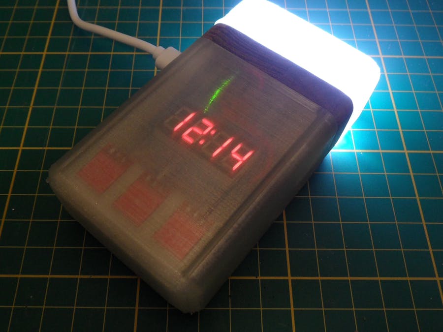
DetailsThis build uses a couple of WS2812B (or better known as Neopixels) to create the sunrise effect. These LEDs will be controlled by an Arduino pro micro that keeps the time using a DS3231 real-time clock. The time can be set on a seven-segment display with the help of capacitive touch buttons.
All parts of this project are available online and could be build using the instructions below.
Thanks to DigitSpace for supplying the parts for this project! DigitSpace sells all kinds of Electronics and kits for makers. Due to a variety of shipping options, they could provide you the parts you need on time for a great price!
Build instructionsStep 1
Start by gathering the materials for this build, the electronics can be found in the part list and the enclosure along the project files. Beside these parts you also need the tools and supplies listed below.
supplies:- Superglue
- Wire
- Solder
- Small M2 screws
- Wire stripper
- Soldering iron
- Screw driver
Electronics and 3D printed parts:
Assembly overview:
Step 2
For this part, you need all electronic parts, the electronics top and bottom frame, and the LED strip mount.
Start by removing the headers from all electronics modules. This step is needed to make sure there is enough room for the electronics inside the case. The easiest way to do this is to cut off all pins up to the black plastic and removing the plastic, this makes it easy to heat every individual pin and taking them out using tweezers.
Next up we glue the top and bottom electronics frame together using some superglue and mount the electronics using some 4mm M2 glues (check the assembly overview for the mounting locations).
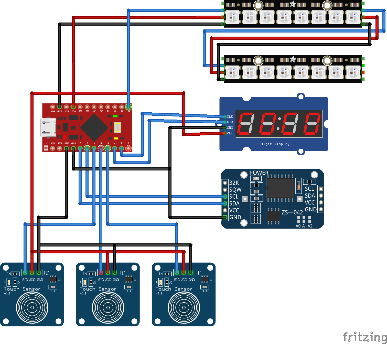
When all electronics are mounted to the frame we can start wiring the electronics using the schematics below. I've looped the power and ground because there is only one power pin available on the Arduino pro micro.
Step 3
Insert the electronics assembly into the front enclosure.
Add the electronic securing tool
Prepare the LEDS mounted on the mounting plate
Solder the LEDs to the Arduino
Take of the LEDs and screw in the mounting plate
Re-attach the LEDs and put on the back cover


Comments
Please log in or sign up to comment.