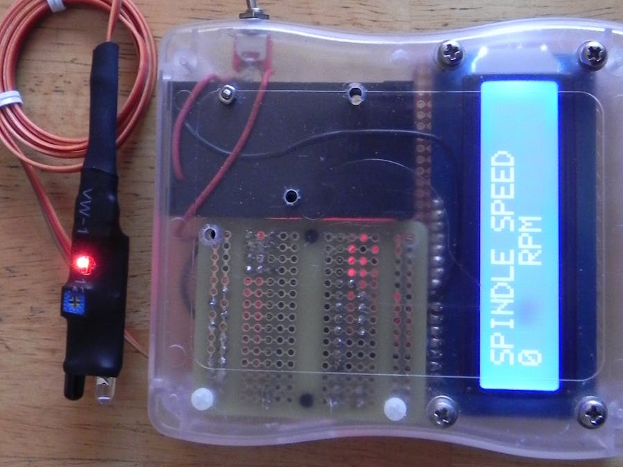
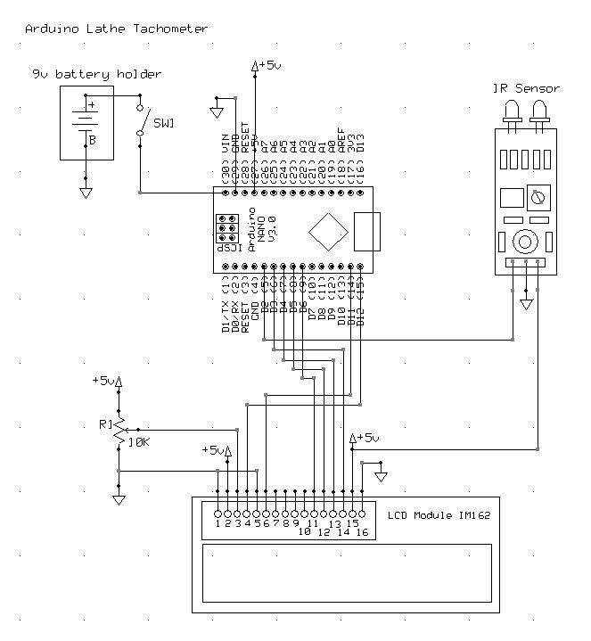
This tachometer is for a WEN 3455 Variable Speed 7” by 12" two-direction bench top metal lathe. You can probably modify it for your own lathe.
Since my lathe didn’t come with a tachometer I decided to make one. I’m a computer programmer and decided to use either a Hall Effect or an Infrared (IR) sensor device with an Arduino and a two line LCD display. I tried the Hall Effect device first because it was very small, but it didn’t work too well at high speeds. The IR device seemed to work better, up to about 1000 rpm. Maybe a faster sensor would be better for over 1000 rpm, but I rarely do any metal work faster than that.
The first thing I had to do was get the Arduino, LCD, and sensor up and running. I put a small strip of label paper on my battery operated hand drill to do the testing at the bench. I used a small motor driven grinding tool to test the higher speeds.
The sensor is going to be wrapped up with heat shrink tubing to protect if from the elements, and it will be put under the side cover of the lathe which keeps the gears protected.
When the side cover of the lathe is off, there is enough room to just glue a post near the main gear, so I made a holder out of Acetal Copolymer round ½ inch Rod. I turned it down a bit to be able to screw the sensor to it, and made a threaded hole for the sensor mounting screw.
I put the sensor here because it’s out of the way of the cover, and the cable has to be routed safely around all the gears and the cover. Pictured is my test setup, it will be all covered up with shrink tubing when the testing is done.
This shows the sensor, and where the wires are routed with cable clamps holding them in place. The clamps are just glued in place with Instant CA Adhesive. Not screwing them down allows the cables to be removed easily for any repairs or modifications to the circuit or code.
The drawn line is where the cover fits on this lathe. I used it to help position the sensor.
The sensor has a small mounting hole and is just screwed onto the post. The screw has a small plastic washer between it and the circuit board. It is just between the two small LEDs on the board.
There is a potentiometer on the board that adjusts the signal distance. You adjust this so that the signals are as clear as possible.
Here, above, you see the two main phases of the build: breadboarding, and mounting all parts to proto boards.
Some things to notice in the following picture:
1. A lot of things are going to be put into the box. I think it was a box for a Raspberry Pi.
2. A proto board was cut down to be soldered onto the LED display. This allows connection to the Arduino.
3. An Arduino Nano was soldered onto a small proto board. Next time I’ll use a socket. If the Nano fails it will be easier to change.
4. The 10K potentiometer was mounted on the proto board and the circuit traces cut so that the plus and minus and wiper when connected wouldn’t cause a short circuit.
5. A small switch and 9 volt battery holder was also soldered into the system.
6. The Nano has to be mounted so that the USB connector can be accessed in case the program has to be changed. A cutout was made in the box to do this.
The IR sensor is all wrapped up. The pot is exposed and the mounting hole is cut out. If the sensor goes bad, get out your sharpest X-Acto blade, and be very careful not to cut wires. This is technical surgery.
Except for the LCD proto board, most everything is mounted with nylon screws, nuts and washers and spacers. You don’t want anything to short out. Measure your LCD, proto boards, battery holder and everything going into the box, then you can order your box. Or you can do what I did, find a box in your enclosure collection and then try to fit everything into it. It's a lot more challenging that way for sure.
Parts ListMany of these things can be purchased on Amazon, Adafruit, or SparkFun.
- OSOYOO 10PCS IR infrared obstacle avoidance sensor module (Amazon)
- KNACRO IIC/I2C/TWI 1602 serial blue backlight LCD module (Amazon)
- Mini Nano V3.0 ATmega328P microcontroller board (Amazon)
- Gikfun solder-able breadboard gold plated finish proto board (Amazon)
- Adafruit Perma-Proto quarter-sized breadboard PCB - single
- 9v battery holder
- 9v battery
- Small toggle switch
- 10K potentiometer for LCD display character brightness
- Enclosure (that can hold everything). The one I used was purchased from SparkFun a long time ago. I think it was for a Raspberry Pi.
- Nylon screws, nuts, washers, and spacers
- Wire
- Shrink tubing


Comments
Please log in or sign up to comment.