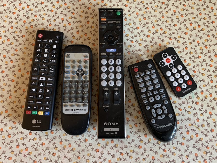
This project allows you to reuse surplus remote controls from old VCRs, TV, DVD players, etc.
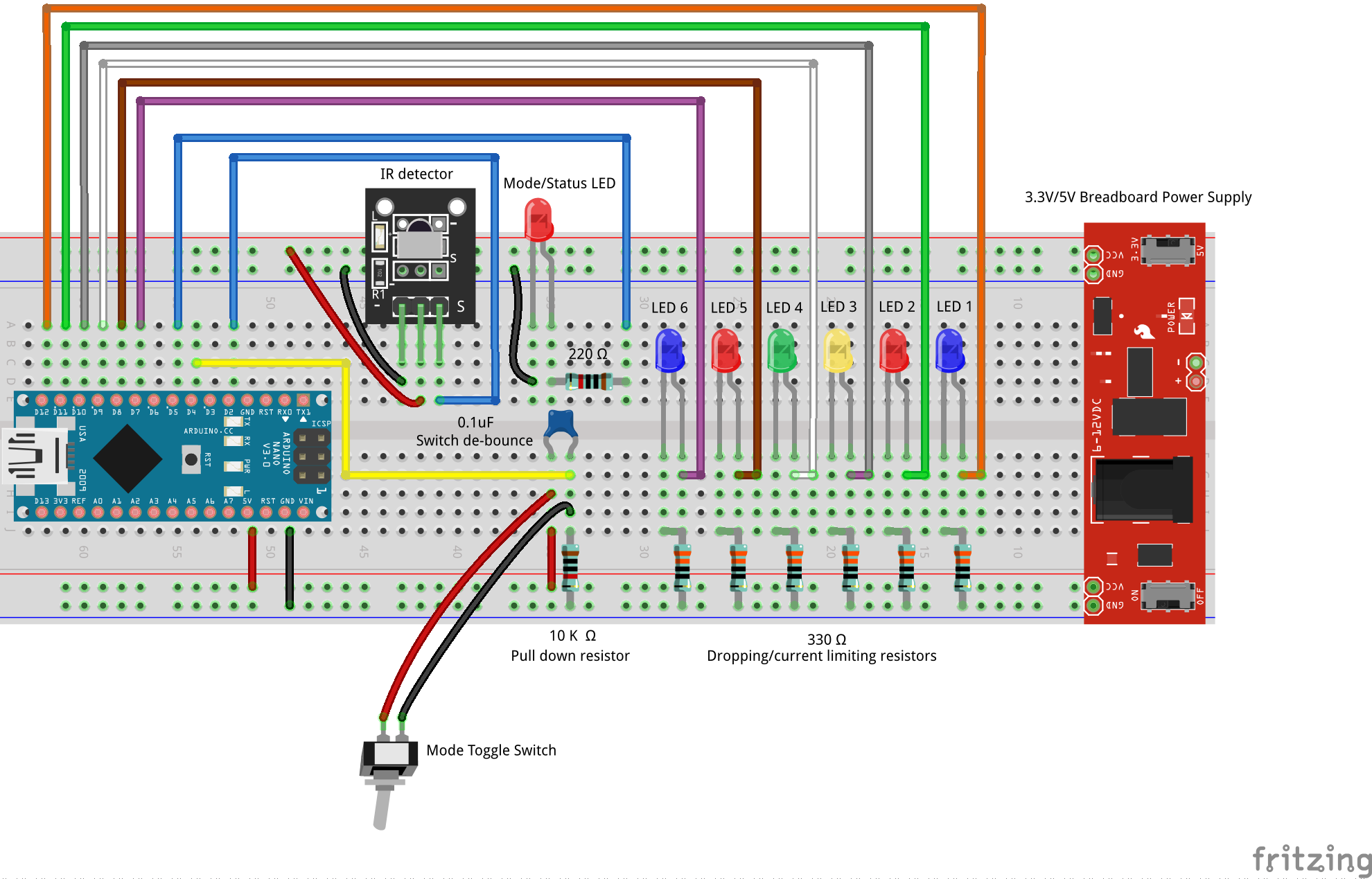
You can use the remotes to turn on devices like lamps, heaters, etc. with relays, power transistors or anything else a 5-volt signal can control. As shown here, it just toggles up to 6 LEDs. The idea is to provide the sketch and breadboard layout so that the signals sent to the LEDs can be sent in parallel to whatever the user imagines!
As designed, it reads 6 IR codes from any remote control and "memorizes" them. I like to use dights 1, 2, 3, 4, 5, 6 -- but any six keys will work. Note that any other key with an IR code other than the 6 known codes acts as a reset and sets all outputs to off. I achieve this by writing the codes as long integers to the EEPROM memory on the Ardunio board. Each one takes 4 bytes, but since the UNO and NANO each have 1024 bytes of EEPROM memory, there's plenty of room. This memory holds through resets and power-offs, as one would expect. The whole thing would fit on a single breadboard, except for the toggle switch. Pins could be soldered to this switch to include it on the breadboard. I was lazy and used tape to hold it on my desk during development.
I've tried it with five different old surplus ones, and they all perform the same. The "gotcha" I struggled with was stray light or weaker signals from some remotes. To solve this, I carefully bent the receiver "LED" downwards to about 45 degrees, and I put a little homemade cardboard and tape box over it, with one end open. It seems to catch the codes consistently and from 5-8 feet away or more. I haven't had a miss in over five days of testing and tweaking the program.
To program it, use the "learn" position. You go from "run" mode to "learn" mode by flipping a toggle switch. This toggle turns on a red mode indicator LED, indicating it's ready to listen. It flashes LED 1, and you press a key on your remote. The flashing LED 1 is programmed to react to that code. As soon as it recognizes the code, it rapidly flashes the mode indicator LED for a second or two (so fast it looks like it's vibrating!) and moves on to the next LED. This continues until all six are programmed. Then the mode indicator LED flashes slowly at one-second intervals indicating the system should be toggled to the run mode.
I found when programming it that the most common mistake was to forget to move your finger to the next digit on the remote. Thus it is easy to program two outputs with the same code. Every time it starts up, it looks for such duplicates. If it finds them, it flashes the "offending" LEDs a few times to suggest re-programming might be necessary. However, a person may want several keys doing the same thing, so it doesn't force re-programming.
Mode status, errors, etc. are indicated by the flash rate of the RED status LED. All the information indicated by the flashing LEDs, etc., is sent to the serial monitor. I set it up to use LED sequences of flashes so it could a user could set it up without a computer. The messages sent to the serial monitor are easier to follow than memorizing what flashing LEDs at various speeds mean. Since this would typically only be programmed a few times, it probably is more natural to hook it up to your PC and watch the text on the serial monitor.
There are a lot of checks and balances in the sketch code. They are well documented (I hope!), so I won't give the details here. Users familiar with C, C++ and the Arduino IDE should easily be able to follow the code and make modifications if desired.
Addendum: I have tested this with 5 relays in parallel with LEDs 1 through 5 and it works as expected. They all toggle a 120 VAC table lamp, so the circuit works as expected. I ran out of relays, so one has to assume the 6th signal will work as well. Note this is just a proof of concept. I had to invert the signals of the first four outputs with a CD4011 quad NAND gate because they close on 0 volts as opposed to 5 volts. The single relay works on a + 5-volt signal, so no signal inversion was needed. Please be careful switching mains voltages. They are high voltage and have the potential to give a bad shock or even kill!
Remember, this is just an example. Use your imagination as to what devices to connect to the 6 outputs. Enjoy!


_3u05Tpwasz.png?auto=compress%2Cformat&w=40&h=40&fit=fillmax&bg=fff&dpr=2)
Comments
Please log in or sign up to comment.