


Hardware components | ||||||
 |
| × | 1 | |||
 |
| × | 1 | |||
 |
| × | 1 | |||
 |
| × | 1 | |||
 |
| × | 1 | |||
 |
| × | 1 | |||
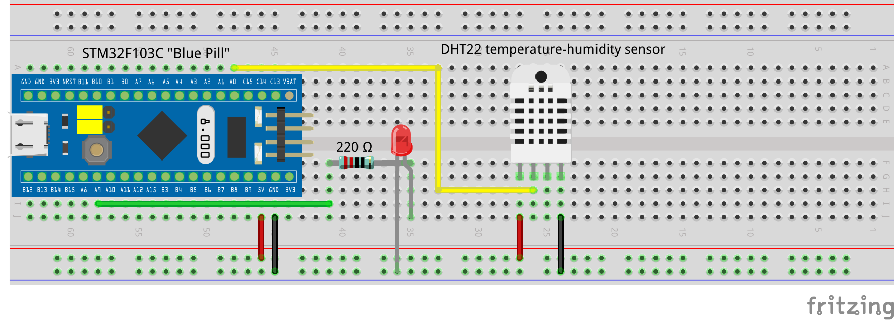
This project is a demonstration of how to use STM32F103C8 boards with the Arduino IDE USB interface. All it does is read a DHT22 temperature/humidity sensor and send the results to the serial monitor... and wink a LED between reading. It's more of a "proof of concept" than a practical application. Hopefully, it will inspire others to develop more complex projects using "blue pill" microcontrollers.
As of March 2020, many STM32 "blue pill" microcontrollers are being shipped with an Arduino compatible bootloader. The Internet suggests a bootloader developed by LeafLabs for Maple mini boards needs to be first flashed on the STM32 using an FTDI programmer before using the USB interface. I have found this to be unnecessary, at least with six STM32F103C8 boards that I have tried. Amazon's documentation says: 'Bootloader (compatible with Arduino IDE) and ''blink'' already installed.' This is correct, in my experience.
These boards are, for the most part, compatible with the Arduino IDE. One has to add the board to the IDE. My development was done with a Mac OS X system, but this should work equally well under a Linux or a Windows-10 environment. These are the steps I used, and I believe them to be platform-independent:
(a) With the Arduino IDE menu: --> File --> Preferences
(b) Add the following link to the "Additional Boards Managers URLs" field:
http://dan.drown.org/stm32duino/package_STM32duino_index.json
(c) Select Tools --> Boards --> Boards Manager
(d) Pick STM32 F103Cxxx and click install
(e) Close the Board Manager and you will find the STM32 board package in the Board menu near the bottom. For the STM32F103C8, check Generic STM32F103C series, and choose:
Variant" "STM3F103C8 (20k RAM. 64k Flash)."
Upload method: "STM32duino bootloader"
CPU Speed(MHz): "72 Mhz (Normal)"
Optimize "Smallest (Default)"
Port: /dev/cu.usbmodem1411301 (Maple Mini)
Note this port is specific to Mac OS X. If you are using Linux or Windows-10, adjust accordingly.
You will note I specified the "Smallest (Default)" optimization level. I did try the following sketch that I found on the Internet. I have lost the link/reference to it, so I can't give credit to the author. My apologies to whoever wrote it.
const float m1[5][5] = { {0.0001, 0.001, 0.01, 0.1, 1},{0.001, 0.01, 0.1, 1, 10},{0.01, 0.1, 1, 10, 100},{0.1, 1.0, 10, 100, 1000},{1, 10, 100, 1000, 10000} };
const float m2[5][5] = { {0.0001, 0.001, 0.01, 0.1, 1},{0.001, 0.01, 0.1, 1, 10},{0.01, 0.1, 1, 10, 100},{0.1, 1.0, 10, 100, 1000},{1, 10, 100, 1000, 10000} };
float m3[5][5];
void setup() {
 Serial.begin(9600);
 delay(100);
}
void loop() {
int j, m, n, p;
unsigned long starttime;
unsigned long endtime;
unsigned long looptime;
while(1 > 0){
starttime = micros();
for(j = 0; j < 1000; j++) {
   for(m = 0; m < 5; m++) {
       for(p = 0; p < 5; p++) {
           m3[m][p] = 0;
           for(n = 0; n < 5; n++) {
               m3[m][p] += m1[m][n] * m2[n][p];
           }
       }
   }
}
endtime = micros();
looptime = endtime - starttime;
Serial.println(looptime);
}
}
These are the results (a smaller number is better.)
Benchmark:
Optimize levels:
Smallest = 309436
Fast (-O1) = 264620
Faster (-O2) = 278837
Fastest (-O3) = 226378
You can try these levels on whatever projects you develop, but remember the chance of errors and unexpected behaviour increase with optimization level.
Finally, we also have to be aware that these boards have different hardware footprints and pinouts than an Arduino Nano. The following diagram shows the "blue pill" pinout:
As you can see, there are equivalent inputs and outputs to the Nano. By carefully studying this diagram, you should be able to replicate the functionality of many Nano based projects with STM32 microcontrollers. Be aware that not all Arduino libraries have been ported to the STM32s. Some will give compiler errors.

Comments
Please log in or sign up to comment.