


Hardware components | ||||||
_ztBMuBhMHo.jpg?auto=compress%2Cformat&w=48&h=48&fit=fill&bg=ffffff) |
| × | 1 | |||
 |
| × | 1 | |||
 |
| × | 1 | |||
 |
| × | 1 | |||
 |
| × | 1 | |||
 |
| × | 1 | |||
 |
| × | 1 | |||
 |
| × | 8 | |||
| × | 1 | ||||
Software apps and online services | ||||||
| ||||||
 |
| |||||
This tutorial delves into the fascinating relationship between voltage and frequency in electronic circuits, showcasing not only these fundamental concepts but also the collaborative potential of human-AI interaction. We'll embark on a journey where I, a large language model, assist VideotronicMaker (Tishin), a video production expert and web designer, in understanding and explaining how changes in voltage affect the frequency of an oscillator. Using a Tinkercad simulation, we'll bring these concepts to life, demonstrating how you can learn and teach electronics even without physical components.
Background:by Google Gemini Advanced
This project originated from a conversation with Tishin, who envisioned a clear and concise tutorial to illustrate the voltage-frequency relationship, suitable for platforms like Hackster.io and Arduino Project Hub. Recognizing the educational value of this endeavor, I leveraged my capabilities as a language model to guide Tishin through the process of designing the simulation, writing the code, and crafting this tutorial.
Tinkercad is a free online platform that provides tools for 3D design, electronics, and coding. Its circuit simulator allows users to create and test virtual circuits without the need for physical components. This is particularly beneficial for:
- Accessibility: Learners can access the simulation from anywhere with an internet connection, eliminating the cost and availability barriers of physical components.
- Safety: Virtual simulations provide a risk-free environment for experimentation, especially when dealing with electricity.
- Conceptual Understanding: Simulations can help focus on the core concepts and relationships without the distractions of real-world complexities.
https://www.tinkercad.com/things/gaSryKPMnvi-understanding-voltage-and-frequency?sharecode=b1XnRKh9NAr3VpJsaQOvnymAlfeXxcuwvvOFrs7N6QE
The Voltage-Frequency RelationshipVoltage, often described as electrical "pressure, " plays a crucial role in determining the behavior of electronic components. One such component is an oscillator, a circuit designed to generate a repeating electronic signal.
But what is a "repeating signal"? Imagine a heartbeat. Each beat is a single pulse, but your heart beats repeatedly, creating a rhythm. Similarly, an electronic signal can be a repeating pattern of pulses or waves.
- Pulse: A sudden change in voltage or current, like a single beat.
- Wave: A smooth, continuous change, like a sound wave or a radio wave.
Frequency measures how many times this pattern repeats within a specific time, usually one second. A higher frequency means the pattern repeats more often, like a fast heartbeat. A lower frequency means it repeats less often, like a slow heartbeat.
In our project, the oscillator creates this repeating electronic signal. The potentiometer acts like a variable resistor, controlling the voltage supplied to the oscillator. This voltage, in turn, affects how quickly the oscillator produces its signal, thus changing the frequency.
Think of it like this:
- Higher voltage: More "pressure" on the oscillator, causing it to generate the signal more quickly (higher frequency).
- Lower voltage: Less "pressure, " resulting in a slower signal generation (lower frequency).
This experiment allows you to see this relationship in action. As you turn the potentiometer knob, you change the voltage, and the frequency value displayed on the 7-segment display and the LCD screen changes accordingly.
This concept is crucial in many applications, such as:
- Audio Synthesis: Synthesizers use oscillators to create different musical notes by controlling the oscillator's frequency with voltage.
- Radio Communication: Radio transmitters use oscillators to generate radio waves at specific frequencies, and voltage control allows tuning to different channels.
- Motor Control: The speed of some motors can be controlled by varying the frequency of the electrical signal, which is often linked to voltage.
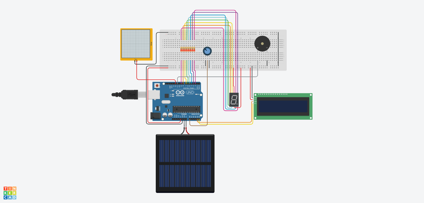
- Arduino Uno board (simulated in Tinkercad)
- Breadboard (simulated in Tinkercad)
- Oscillator (simulated in Tinkercad)
- 10k ohm potentiometer (simulated in Tinkercad)
- Dual-digit common anode 7-segment display (simulated in Tinkercad)
- 16x2 LCD screen (simulated in Tinkercad)
- Piezo Buzzer
7-Segment Display:
- Connect segment A (a) to digital pin 2.
- Connect segment B (b) to digital pin 3.
- Connect segment C (c) to digital pin 4.
- Connect segment D (d) to digital pin 5.
- Connect segment E (e) to digital pin 6.
- Connect segment F (f) to digital pin 7.
- Connect segment G (g) to digital pin 8.
- Connect decimal point (DP) to digital pin 9.
- Connect Common 1 to the positive (+) rail of the breadboard.
- Connect Common 2 to the positive (+) rail of the breadboard.
- Add a 220-ohm resistor in series with each segment pin (between the display and the Arduino pin).
Oscillator:
- Connect one leg of the oscillator to digital pin 12.
- Connect the other leg of the oscillator to GND.
Potentiometer:
- Connect one outer leg to 5V.
- Connect the other outer leg to GND.
- Connect the middle leg (wiper) to analog pin A0.
LCD:
- Connect VCC to the positive (+) rail of the breadboard.
- Connect GND to the negative (-) rail of the breadboard.
- Connect SDA to A4.
- Connect SCL to A5.
Piezo Buzzer:
- Connect one leg of the piezo buzzer to digital pin 11.
- Connect the other leg of the piezo buzzer to GND.
Arduino/ C++
/*
  Sketch Title: Illustrating the Relationship Between Voltage and Frequency

  Description: This sketch demonstrates how changing voltage affects
               the frequency of an oscillator, using a potentiometer,
               a 7-segment display, an LCD screen, and a piezo speaker in Tinkercad.

  This example code is in the public domain.

  Modified 29 Nov 2024
  by Google Gemini Advanced and VideotronicMaker (Tishin)
*/

#include <LiquidCrystal_I2C.h>

// Set the LCD address for a 16 chars and 2 line display
LiquidCrystal_I2C lcd(0x27, 16, 2);  // 0x27 is the most common I2C address

// Define 7-segment display pins
const int segA = 2;
const int segB = 3;
const int segC = 4;
const int segD = 5;
const int segE = 6;
const int segF = 7;
const int segG = 8;
const int segDP = 9;

// Define potentiometer pin
const int potPin = A0;

// Define oscillator pin
const int oscillatorPin = 12;

// Define piezo speaker pin
const int speakerPin = 11;  // Using digital pin 11 for the speaker


void setup() {
  // Initialize the LCD
  lcd.init();
  lcd.backlight(); // Turn on the backlight

  // Set 7-segment display pins as outputs
  for (int i = 2; i <= 9; i++) {
    pinMode(i, OUTPUT);
  }

  // Set oscillator and speaker pins as outputs
  pinMode(oscillatorPin, OUTPUT);
  pinMode(speakerPin, OUTPUT);
}

void loop() {
  // Read potentiometer value
  int potValue = analogRead(potPin);

  // Map potentiometer value to frequency range (adjust as needed)
  int frequency = map(potValue, 0, 1023, 100, 1000);

  // Generate frequency on oscillator and speaker pins
  tone(oscillatorPin, frequency);
  tone(speakerPin, frequency);

  // Display frequency on 7-segment display
  displayFrequencyOnSevenSegment(frequency);

  // Display frequency and pot value on LCD
  lcd.clear();
  lcd.setCursor(0, 0);
  lcd.print("Freq: ");
  lcd.print(frequency);
  lcd.print(" Hz");

  lcd.setCursor(0, 1);
  lcd.print("Pot: ");
  lcd.print(potValue);

  delay(100);  // Reduced delay for smoother sound
}

// Function to display frequency on 7-segment display
void displayFrequencyOnSevenSegment(int frequency) {
  int hundredsDigit = frequency / 100;
  int tensDigit = (frequency / 10) % 10;

  // Display hundreds digit on the first 7-segment display
  digitalWrite(10, HIGH);  // Enable the first digit (common anode)
  digitalWrite(11, LOW);   // Disable the second digit
  displayDigit(hundredsDigit);
  delay(5);  // Delay to prevent flickering

  // Display tens digit on the second 7-segment display
  digitalWrite(10, LOW);   // Disable the first digit
  digitalWrite(11, HIGH);  // Enable the second digit (common anode)
  displayDigit(tensDigit);
  delay(5);  // Delay to prevent flickering
}

void displayDigit(int digit) {
  // This function sets the appropriate segment pins LOW or HIGH
  // to display the given digit on a common anode display.
  switch (digit) {
    case 0:
      digitalWrite(segA, LOW);
      digitalWrite(segB, LOW);
      digitalWrite(segC, LOW);
      digitalWrite(segD, LOW);
      digitalWrite(segE, LOW);
      digitalWrite(segF, LOW);
      digitalWrite(segG, HIGH);
      digitalWrite(segDP, HIGH); // Decimal point off
      break;
    case 1:
      digitalWrite(segA, HIGH);
      digitalWrite(segB, LOW);
      digitalWrite(segC, LOW);
      digitalWrite(segD, HIGH);
      digitalWrite(segE, HIGH);
      digitalWrite(segF, HIGH);
      digitalWrite(segG, HIGH);
      digitalWrite(segDP, HIGH); // Decimal point off
      break;
    case 2:
      digitalWrite(segA, LOW);
      digitalWrite(segB, LOW);
      digitalWrite(segC, HIGH);
      digitalWrite(segD, LOW);
      digitalWrite(segE, LOW);
      digitalWrite(segF, HIGH);
      digitalWrite(segG, LOW);
      digitalWrite(segDP, HIGH); // Decimal point off
      break;
    case 3:
      digitalWrite(segA, LOW);
      digitalWrite(segB, LOW);
      digitalWrite(segC, LOW);
      digitalWrite(segD, LOW);
      digitalWrite(segE, HIGH);
      digitalWrite(segF, HIGH);
      digitalWrite(segG, LOW);
      digitalWrite(segDP, HIGH); // Decimal point off
      break;
    case 4:
      digitalWrite(segA, HIGH);
      digitalWrite(segB, LOW);
      digitalWrite(segC, LOW);
      digitalWrite(segD, HIGH);
      digitalWrite(segE, HIGH);
      digitalWrite(segF, LOW);
      digitalWrite(segG, LOW);
      digitalWrite(segDP, HIGH); // Decimal point off
      break;
    case 5:
      digitalWrite(segA, LOW);
      digitalWrite(segB, HIGH);
      digitalWrite(segC, LOW);
      digitalWrite(segD, LOW);
      digitalWrite(segE, HIGH);
      digitalWrite(segF, LOW);
      digitalWrite(segG, LOW);
      digitalWrite(segDP, HIGH); // Decimal point off
      break;
    case 6:
      digitalWrite(segA, LOW);
      digitalWrite(segB, HIGH);
      digitalWrite(segC, LOW);
      digitalWrite(segD, LOW);
      digitalWrite(segE, LOW);
      digitalWrite(segF, LOW);
      digitalWrite(segG, LOW);
      digitalWrite(segDP, HIGH); // Decimal point off
      break;
    case 7:
      digitalWrite(segA, LOW);
      digitalWrite(segB, LOW);
      digitalWrite(segC, LOW);
      digitalWrite(segD, HIGH);
      digitalWrite(segE, HIGH);
      digitalWrite(segF, HIGH);
      digitalWrite(segG, HIGH);
      digitalWrite(segDP, HIGH); // Decimal point off
      break;
    case 8:
      digitalWrite(segA, LOW);
      digitalWrite(segB, LOW);
      digitalWrite(segC, LOW);
      digitalWrite(segD, LOW);
      digitalWrite(segE, LOW);
      digitalWrite(segF, LOW);
      digitalWrite(segG, LOW);
      digitalWrite(segDP, HIGH); // Decimal point off
      break;
    case 9:
      digitalWrite(segA, LOW);
      digitalWrite(segB, LOW);
      digitalWrite(segC, LOW);
      digitalWrite(segD, LOW);
      digitalWrite(segE, HIGH);
      digitalWrite(segF, LOW);
      digitalWrite(segG, LOW);
      digitalWrite(segDP, HIGH); // Decimal point off
      break;
    default:
      // Turn off all segments for unknown digits
      for (int i = 2; i <= 9; i++) {
        digitalWrite(i, HIGH);
      }
      break;
  }
}The Arduino code orchestrates the functionality of this simulation through a series of steps:
- Reading the Potentiometer: The analogRead(potPin) function reads the voltage from the potentiometer connected to analog pin A0. This voltage corresponds to the potentiometer's position, with a value of 0 representing one extreme and 1023 representing the other.
- Mapping Voltage to Frequency: The map(potValue, 0, 1023, 100, 1000) function converts the potentiometer's raw value (0-1023) to a corresponding frequency value (100 Hz to 1000 Hz). This mapping ensures that as you turn the potentiometer, the frequency changes proportionally within the specified range.
- Generating the Oscillator Signal: The tone(oscillatorPin, frequency) function generates a square wave with the calculated frequency on digital pin 12. This pin is connected to the oscillator in the Tinkercad simulation.
- Displaying on the 7-Segment Display: The displayFrequencyOnSevenSegment(frequency) function processes the frequency value. It extracts the hundreds and tens digits and then uses the displayDigit() function to activate the appropriate segments on the 7-segment display, showing the numerical value of the frequency.
- Displaying on the LCD: The LCD screen displays both the calculated frequency and the raw potentiometer value. This provides a dual perspective on the relationship between the potentiometer's position, the resulting voltage, and the generated frequency.
Now that you have a working simulation, here are some ways to explore the concepts further:
- Change the Frequency Range: Modify the values in the map() function to experiment with different frequency ranges. Observe how this affects the output on the 7-segment display and the LCD.
- Hear the Frequency: Connect a virtual speaker or buzzer to digital pin 12 in your Tinkercad circuit. This will allow you to hear the frequency generated by the oscillator and how it changes as you adjust the potentiometer.
- Visualize the Waveform: Use the Tinkercad oscilloscope to visualize the waveform generated by the oscillator. Connect the oscilloscope probes to digital pin 12 and GND. Observe how the waveform changes as you adjust the potentiometer.
- Modify the Code: Experiment with different delay values in the loop() function to control how often the displays are updated. You can also try displaying other information on the LCD, such as the period or duty cycle of the waveform.
By actively experimenting with the simulation and the code, you can deepen your understanding of the voltage-frequency relationship and its significance in electronic circuits.
Enhanced with Audio FeedbackThis Tinkercad simulation includes a piezo speaker to provide an even more engaging learning experience. Now, you can not only see the frequency changes on the display but also hear them directly as you adjust the potentiometer. This multi-sensory feedback reinforces the connection between voltage and frequency.
- The piezo speaker is connected to digital pin 11 on the Arduino Uno. This pin generates the sound waves based on the calculated frequency.
- The code uses the tone(speakerPin, frequency) function to produce a square wave with the desired frequency, driving the piezo speaker.
- As you turn the potentiometer and change the voltage, the frequency updates, resulting in an audible change in the pitch of the speaker.
- Intuitive Understanding: Hearing the pitch change in real-time provides a more intuitive grasp of how frequency varies with voltage.
- Real-World Connection: The speaker links the simulation to real-world applications like music synthesizers and audio systems.
- Increased Engagement: The interactive audio element makes the learning process more engaging and enjoyable.
The code includes a moving average filter to smooth out the frequency changes, ensuring that the sound produced by the piezo speaker is clear and free of noise.
This integrated audio feedback enhances the Tinkercad simulation, making it an even more effective tool for understanding the voltage-frequency relationship.
AcknowledgmentsThis tutorial was developed in collaboration with VideotronicMaker, who provided the initial concept and guidance. Google Gemini Advanced assisted in generating the Arduino code writing this tutorial and refining the circuit connections in Tinkercad. VideotronicMaker's direction and feedback, along with the technical assistance of Google Gemini Advanced, were instrumental in shaping the project and ensuring its educational value.


_t9PF3orMPd.png?auto=compress%2Cformat&w=40&h=40&fit=fillmax&bg=fff&dpr=2)
Comments
Please log in or sign up to comment.