


Hardware components | ||||||
_ztBMuBhMHo.jpg?auto=compress%2Cformat&w=48&h=48&fit=fill&bg=ffffff) |
| × | 1 | |||
 |
| × | 1 | |||
 |
| × | 1 | |||
 |
| × | 1 | |||
 |
| × | 1 | |||
 |
| × | 1 | |||
Software apps and online services | ||||||
 |
| |||||
Hand tools and fabrication machines | ||||||
| ||||||
This project is for Arduino juniors. It's really easy to make, code, and buy, as it's really inexpensive. I've also added detailed explanations as to why everything happens the way it does.
Project OutlineToday, you're going to assemble an LED circuit in Arduino. First project? Nervous? That's OK, that's more than OK, seeing as I made this project for YOU, and all other Arduino beginners. Right, so once this is done, you're going to press a button, and two lights that were on will turn off. Release it, and they'll turn on. This is how all Arduinoers all start out, well, actually they just turn one on first. So your first project will be better than most. Let's GO!
Powering the BoardThis step is SO easy. Get you're board, the thing called the Arduino Uno, and the longish wire, the USB connector. Let's take a look at the board. We have:
As you can see in the image above, the Uno is pretty complicated, but don't worry, you'll get the hang of it.
Now, take the chance to look at the USB connector. Don't bother looking at the wire, that goes all the way through. Look at the ends. Hold them up beside each other. One is thin: this is the classic USB mouth. Go RIGHT ahead and plug it into the computer. Look at the remaining end. It's in a weird shape you may not have seen before in wires but take a look. Where do you think it goes?
Hint: look at the Uno and the diagram above.
That's right! It goes into the metal box, or the place labelled '1' on the diagram. Plug it in. You will now see (assuming that your computer is not in shutdown) that a red light comes on and a green light near it flashes. This means that your computer is powering the board board, and all is well.
Adding the BasicsRight. Board powered. One step done. Great Now for the fun bit.
Grab your breadboard (the plastic sheet with loads of holes in it). let's have a look. There are two things to remember while using breadboards, those being:
So what does it do?
Breadboards are useful. What they do in simple words, is, they carry electricity. So let's say that I need to carry a current from one thing to another. I would put the entering voltage in one end, and the exiting voltage in the other. But let's start.
Grab the two LEDs. LED stands for Light Emitting Diode. Lay the breadboard out in front of you, so one of the ends that have a red '+' and a blue '-' are facing you. Then take note of how the LED has legs of different lengths; one short and one long. For future reference, the long leg means the one to put the current into, and the short means ground or earth, which is in short, how the current stays connected with the rest of the circuit. So put the first LED into one of the sides down the outside, putting the longer leg into the column with the plus sign on it, and the short to minus. Do the same for the other side, with the other LED, connecting the same legs to the same holes as last time.
Great. Two LEDs in place. Now for the BUTTON!
Now look at the button. It should look something like this:
However, we need this in the breadboard. We currently have a problem: the legs are bent and don't fit the holes of the breadboard properly. So, we'll have to straighten the legs. Get your long-nosed pliers and put one of the legs in them, ensuring that they are the same way as the pliers. Now... SQUEEZE! If you notice, when removing the pliers that the leg is straight, but not facing directly down from the button body, grab the pliers and adjust that. Once done, repeat for all other legs on the button.
Now with that done, you can go and put that on the breadboard.
Put it on the top row of the left set of horizontal buses.
Great. Now for the wires.
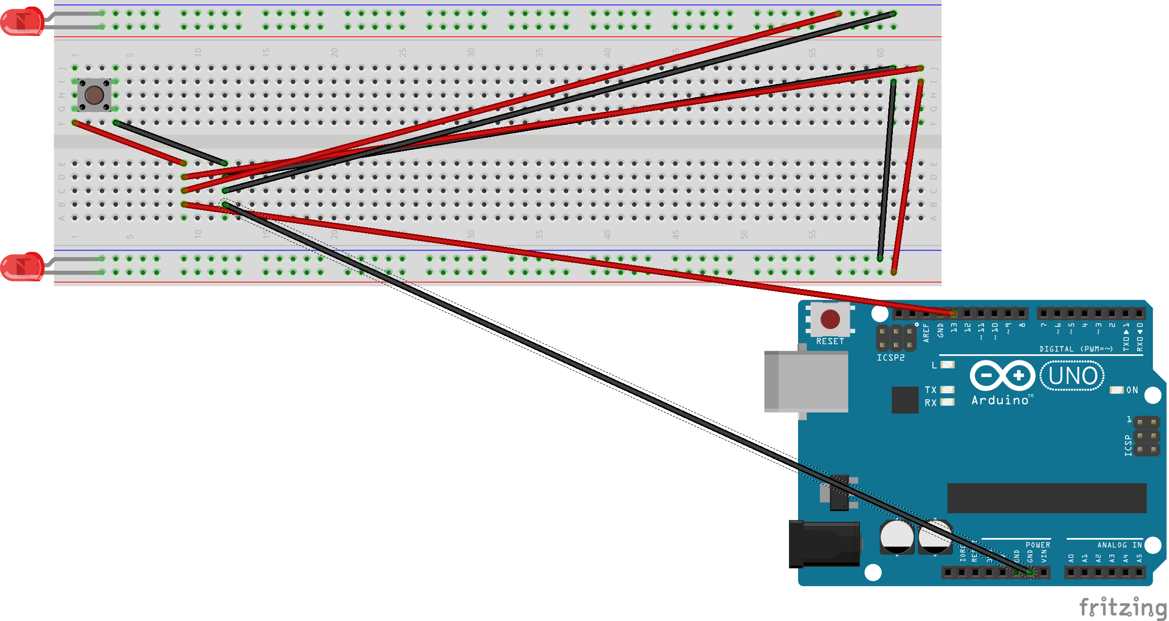
WiringNow this is very slightly complicated. So, on every step, remember to compare from the last picture to see which wire to add. To start, get a wire and put it on like this:
Put another wire like this:
Now two more:
Now follow the next few pictures.
Done!
CodingWith the wiring/assembling done, you now have to program your Uno. Here's how. Scroll down this page until you get to the section marked 'Code'. When you do, copy the code you see (the bunch of writing which makes no sense) by highlighting it and pressing CTRL+C on Windows and Command+C on a mac.
Now open Arduino IDE. There will probably be code already in there. Delete it. Now press CTRL+V (Win) or Command+V (Mac). This will copy the code you had here to Arduino IDE. Hooray! With that done, make sure that your Uno is connected. Then, from the top toolbar, click Tools>Boards and click Arduino Uno. Go back into Tools and click Ports. Click the one that you Arduino board is in. Now, you're done! Near the toolbar, you'll see the final button: Upload (->), and feel the joy as Arduino IDE uploads the code to your robot. Now, we just need to use it. Go to the next step and follow the instructions.
RunningCongratulations! You have now practically finished this tutorial all you need to do is this one last step. The lights on your breadboard should be off. Now all we need to do is this. Click Tools on the toolbar. From the list, click Serial Monitor. A small window should pop up it will look like this:
In computer programming, 0 means off and 1 means on. So what you see in this is basically a digital switch. So, to turn on all you have to do is enter '1' in the top bar. You can now do a countdown to this project working. 3... 2... 1... Click the button next to the bar that says 'Send'. If everything worked, THE LIGHTS SHOULD TURN ON! Well done. And if you press the button, they turn off!
Why it HappenedWhat happened?
Okay. What really happened was that when you entered '1' into the digital switch, it followed what I programmed and sent a current to pin 13 on your Uno. That current then flowed into the lights, turning them on. But when you pressed the button, the light turned off, as the current was interrupted.


_3u05Tpwasz.png?auto=compress%2Cformat&w=40&h=40&fit=fillmax&bg=fff&dpr=2)
Comments
Please log in or sign up to comment.