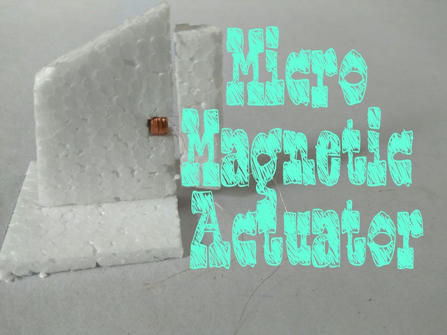
Today I am sharing a tutorial of micro magnetic actuator for RC foam plane's Aileron and Rudder control. I have used an Arduino to test it and it worked really well, You can use RC transmitter and receiver too. There are many actuators available online but they are too costly so I decided to make my own. Not very hard takes about 15-20 minuets to complete the build including the testing circuit.
About the parts used:-All the parts can be found at UTSource.
- Arduino UNO :- Will be used to control the actuator. (Amazon Link)
- Bread Board :- Used for prototyping. (Amazon Link)
- A Straw or small Paintbrush :- To wind wire around to make small coil (Amazon Link)
- Small cardboard piece :- To use as a stopper for coil.
- L293D dual H bridge IC :- Used to connect coil as it cannot be connected to arduino directly. (Amazon Link)
- Bread board Jumpers and male to male wires.
- Thin copper wire. :- It will be used for coil, I got mine from a broken clock (Amazon Link)
- 2 small neodymium magnets :- I have salvaged from broken earphones (
Amazon Link)
This step is for beginners who don't know much about arduino and motor drive IC. You can refer to the Images provided to know the Pinouts of the board and L293D. Arduino is a microcontroller and L293D is a motor drive IC. Here the PWM (pin 11) of arduino is used to control the power for the actuator and pins 9 and 10 are used to control the directions. The code will be provided at the end of this post.
L293D is used to control the coils direction, an H-bridge is used as the coil cannot be connected to the Arduino directly. the direction pins 9 & 10 are connected to input 1 and 2 of the L293D. and PWM pin 11 is connected to enable 1. more about connection later.
Making the Actuator : -Making an actuator is very simple. you just need a copper wire from old clock follow the steps :-
- Take the straw/paintbrush and put the small cardboard piece on it like in the picture above.
- Now wind the wire around the Straw/brush, make about 400-450 turns.
- As you are winding the wire, use some white glue to stick the wires in place. just a little.
- Once the coil is made apply glue around it and let it dry. then slowly and gently slide the cardboard piece over the straw/brush so that the coil is free.That's all about the coil.Now you need to make an arm for the actuator. For that you can use a small strip of cardboard or plastic and place the two magnets to the strip.Refer the Picture above for the Idea.
- Place the L293 on breadboard and make connections as shown in the Diagram above. connect the Vcc to +ve and ground pins to -ve.
- Connect Pin 11 of arduino to pin 1 (enable1) of L293D.
- Connect Pins 9 and 10 of arduino to Input pins of the IC.
- Connect arduino's 5v to +ve and Ground to -ve. Thats all.
- Now next step is to write and upload the code.
Here is the controlling /testing part. You can use a receiver to directly connect the actuator or use Arduino to test it. Code is very simple and basic. Here if you want to increase or decrease the power of the actuator or have position control you can reduce or increase the PWM value of "en" you can keep it anywhere between (0-255)
If you have any problem/questions feel free to ask. thank you.
CODE:-
/*
 *Code By Harsh Dethe
*/
int en = 11;
int R = 10;
int L = 9;
void setup()
{
    pinMode(L, OUTPUT);
    pinMode(R, OUTPUT);
    pinMode(en, OUTPUT);
}
void loop()
{
    analogWrite(en,200);
    digitalWrite(R,HIGH);
    delay(1000);
    digitalWrite(R,LOW);
    analogWrite(en,200);
    digitalWrite(L,HIGH);
    delay(1000);
    digitalWrite(L,LOW);
}


Comments
Please log in or sign up to comment.