


Hardware components | ||||||
_ztBMuBhMHo.jpg?auto=compress%2Cformat&w=48&h=48&fit=fill&bg=ffffff) |
| × | 2 | |||
 |
| × | 10 | |||
 |
| × | 1 | |||
 |
| × | 2 | |||
 |
| × | 2 | |||
 |
| × | 4 | |||
I want to show you how to connect two (or more) independently programmable Arduinos to one computer.
Džejkop on YouTube (no sound):
put up a video that confirmed for me that we can attach multiple Arduinos to one computer. Thanks to him for that.
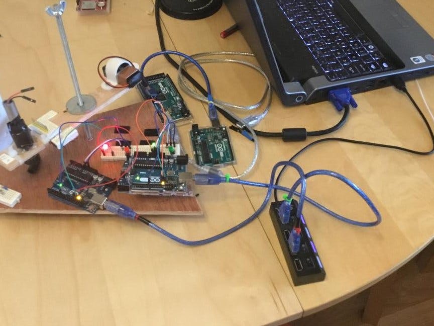
The main photo shows TWO Arduino UNOs attached.
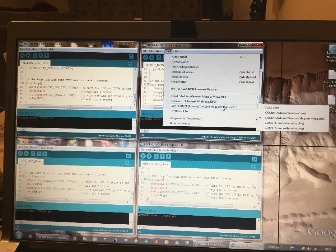
Bottom photo shows Arduino menu proving that I have attached 3 UNOs and a Mega 2560 all at the same time as independently programmable connections.
How is it done?
Perhaps the easiest way to describe it is to think of the browser you are presently using to look at this Arduino Project.
Most people will be aware that you can open a browser by clicking on a menu link or an icon. From this you can then open Tabs, which are linked to 'that specific opened browser'.
Now, imagine that you have one browser open and want to open a second instance, or window, that is NOT a Tab. The common way to open a new 'instance' of the program, is to click on the Menu link or icon, for each 'separate' window.
By the same process, to attach more than one Arduino to the same computer and be able to program them independently, open your first Arduino IDE window and connect it to your first Arduino as normal, e.g. COM 11.
After that, plug in your second Arduino and click on the Menu/icon and open a brand new instance of Arduino IDE. Immediately, you will note that it does take the same COM 11 number of the first instance. This is what confuses people into thinking this cannot be done.
However, if you now go to the Menu bar at the top and click on Tools, followed by Port:, you will now see all the COM options. Showing, for example, COM 11 and COM 23.
Attach your second Arduino to COM 23. Repeat the process for any new Arduino you attach.
There you are, now you can attach as many Arduinos as you have ports.
WARNING, though. Remember, the more Arduinos you attach to one computer, the more power it has to supply to maintain the 5 Volts to each. This increases the power requirements of the computer and overload by attaching too many at once could, in theory, lead to burning out your computer.
So be careful.
In addition, whilst you can program each attached Arduino, for the same reason, it is not advisable to have them simultaneously power the full circuits you want to attach to them - remember to plug in a separate power source for each Arduino if you are also wanting to have them run circuits while you edit and save.
For this demonstration, however, there is only one LED as the ‘circuit’ and only two Arduinos attached to the Laptop, so demand is easily manageable.
Lastly, whilst I have suggested you can fill each of your computer ports with an independent Arduino, I advise against going beyond 4 at a time, even as an experiment.
Now, actually doing it with two Arduino UNOs:
First, we want to be certain we can easily identify, externally and rapidly, which Arduino is connected to which USB port.
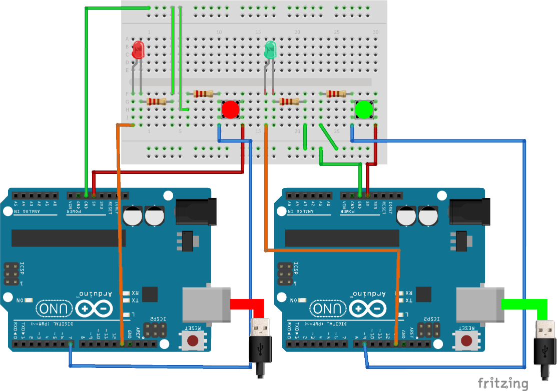
My own method of doing that is to name these two Arduinos as RED and GREEN, as one has a red LED the other a green LED, in their circuit.
Because I am using a 4-port USB hub for the ports I also obtained coloured cable-ties and momentary-press buttons (see the image at the top) and put a red cable-tie at each end of the red cable, with a red button and LED on the breadboard, but they are not 'necessary'.
Same process for the GREEN Arduino port connections.
Whatever you do, get into a habit of making the physical side as easily identifiable as the program side - in your own way, as you can accidentally send the wrong code to an Arduino. This might just be an inconvenience, but if you didn't realise you'd done it, the circuit will not do what it is supposed to.
For the purposes of this demonstration of connecting multiple Arduinos, the programs for both RED and GREEN are the same. that is not necessary, but if connecting multiple boards, you might expect the programs, boards and circuits to have some working relationship, once you understand how it all works.
Yes, I know that's not a done deal, you might just want to work on different projects at the same time, or impress someone with your extreme computing skills.
For me, my Dohmino device [update 16/04/2020. (remember, I am still new at this) It turns out that the 'Dohmino' device is already well known and used. It is two optocouplers , but no project I have come across, anywhere, has used it to do what my Arduino linking project will do, so my idea is still valid - more to come]. Hence I will used ready made optocouplers intended to bring this process even more importantly connected in the future, as I will be programming at least three operation-related Arduinos at the same time, as I 'travel' around the network of communicating and working Arduinos.
Two Arduinos independent on one PC

Comments
Please log in or sign up to comment.