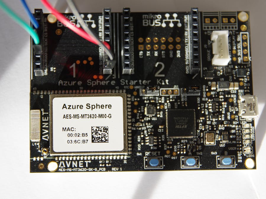
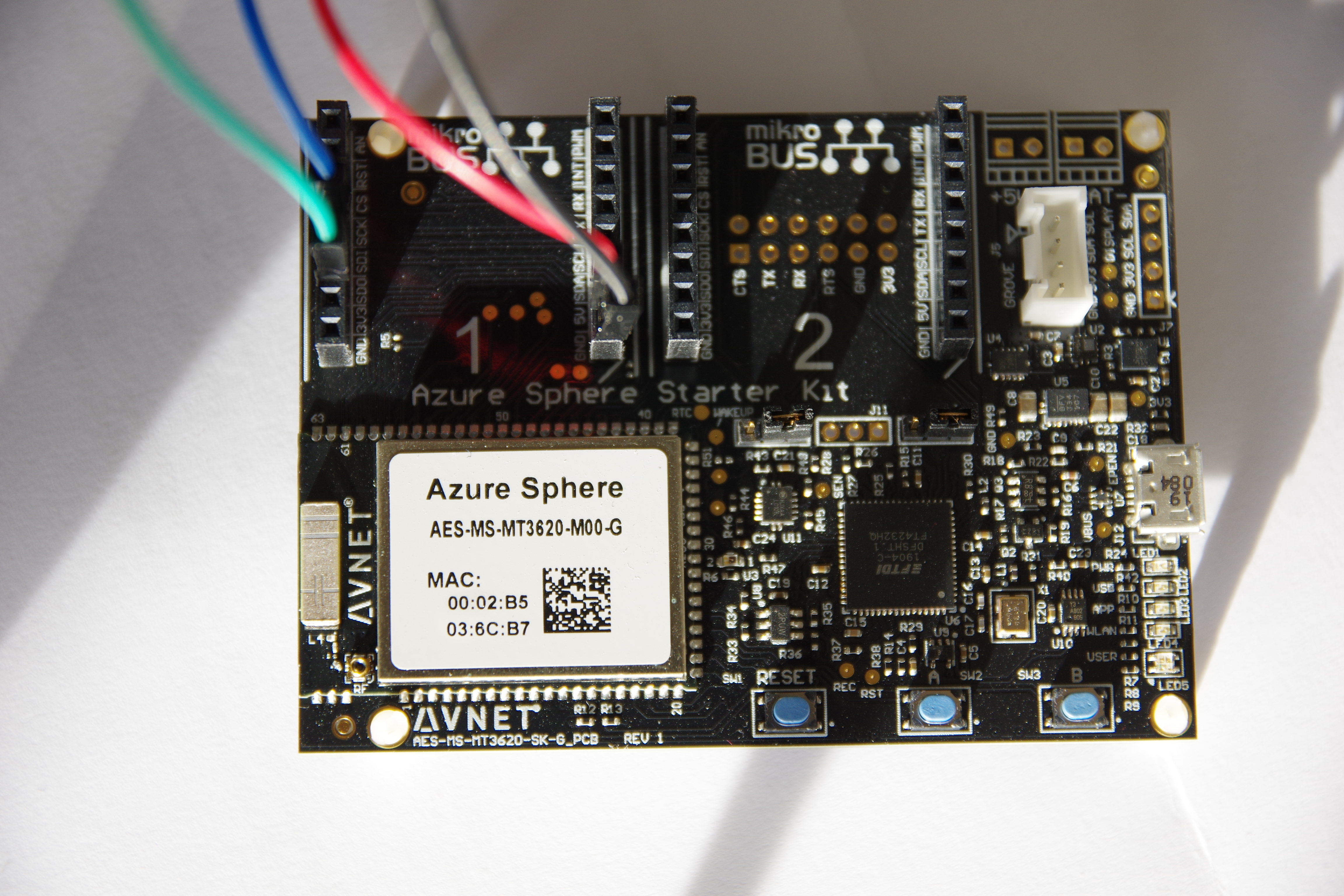
- Setup your Azure Sphere Device: Setup
- Checkout the code from my Repository
Use the following wiring to connect passive leds to the board:
Single RGB led
- Connect the color channels to 3 PWM-enabled GPIO pins
- Connect the leds ground to a ground pin
RGB led strip
- Connect 3 PWM enabled GPIO-pins to your booster circuit
- Connect the boosters output to your led-strip
- Connect the boosters positive input to a power-supply
- Connect the the boosters ground to the power supply and to the Sphere's ground
Programming
- Find the controller_id and the ids of the pins you connected to. For the starterkits onboard RGB-led, it's 2 as controller_id and 0, 1 and 2 as r, g, b pins.
- Add
"Pwm": [ "PWM-CONTROLLER-{yourControllerId}" ]to the applications manifest capabilities - Add the setup and teardown methods:
SetupPwm(unsigned int controller_id, uint32_t redPin, uint32_t greenPin, uint32_t bluePin);
Teardown();- Set the desired color by using the color-struct or by setting the values directly
SetColor(struct Color color);
SetColorFromInt(int red, int green, int blue);
SetColorFromBytes(uint8_t red, uint8_t green, uint8_t blue);Wiring
- Connect the SPI-CLK (SCK on the starter-kit) pin to the led's CI (clock in) connection.
- Connect the SPI-MOSI (SDO in the starter-kit) pin to the led's DI (data in) connection.
- Connect the led's 5v to a power supply or the boards 5v output. Make sure your power-source provides enough power for the leds and reasonable sized cables. Apa102 use high current and low power, so take extra care handling the power. If you use long strips make sure you feed power from both sides and use correct cables for the currents.
- Connect the led's GND to the power supply and to Sphere's GND pin
Programming
1. Find the interface_id and the chipselct_id of the interface you used. For the Mikrobus connectors on the starter-kit it's 1 as interface_id and -1 as chipselect_id.
2. Add "SpiMaster": [ "ISU{interface_id}" ] to the applications manifest capabilities.
3. Add the setup and teardow methods:
SetupApa102(int interfaceId, int chipSelectId);
Teardown();
4.1. Set the whole strip to a color:
SetSolid(struct ColorWithBrightness color, int length);4.2. Set the whole strip to custom colors:
SetCustom(struct ColorWithBrightness *color, int length);4.3. Stream colors to the leds, from the first to the last:
PrepareForStreaming();
while(?)
{
  AppendColor(struct ColorWithBrightness color);
}
FinishStreaming();- Make sure you claimed your device and installed the SDK (see Setup)
- Use your own code or uncomment exactly one line in main.c
- Connect your sphere using USB
- Build the solution
- Use the green "Remote GDB Debugger" button to upload the code to your device
- Enjoy
- Build Errors: Fix them. (There is no common solution)
- Colors messed up in PWM: Switch the pin_ids so they work correct.
- PWM doesn't light up: Make sure the are common ground or make sure your booster circuit works correctly
- APA102 don't light up: Measure the power in the strip and make sure everything is wired correctly. Don't use long cables between the first led and the GPIO pin.
- APA102 light up randomly: Make sure all involved GND are connected together. Make sure data and clock are connected correctly.
- APA102 colors messed up: Find the color configuration for your strip in the datasheet or by trial and correct the color order in Apa102Control.c


Comments
Please log in or sign up to comment.