Sometimes we need to build a smaller circuit for our projects, but unfortunately, if we use a breadboard or perforated copper board for project, the size of the project will become larger, so to overcome this issue, we must go for PCB. But to build PCBs, it takes much time. Hence, in this tutorial, I will show you how to design your PCB by using CD marker, which will overcome time and pain of designing it in computer software like Eagle, Diptrace, Fritzzing, KiCAD, Tina and also cost effective too.
By using this technique, we can build our wearables easily in less time. So, let us get started.
Step 1: A Small introduction to WearablesThe phrase wearable technology, or wearables, refer to electronic technologies or computers that are incorporated into watch, bracelets, helmets, gloves, cloths, shoes, glasess, etc.
Generally, wearable technology will have some form of communication ability and will allow the wearer access to information in real time. Data-input capabilities are also a feature of such devices, as is local storage. The purpose of wearable technology is to create constant, convenient, seamless, portable, and mostly hands-free access to electronics and computers.
Step 2: Watch these Videos!Step 3: Components Required!It's up to you whether you are building simple project or just an ATtiny IC programmer; you can choose your components based on your need.
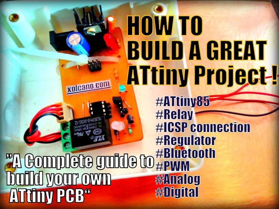
Before starting this project, I thought of making only ATtiny Programmer with just ICSP connection in it, later I added male headers for GPIO pins (General Purpose Input Output). Then I added 7805 voltage regulator to it, so that we can directly connect to12V source. While designing PCB, I added 5V relay which can control 220V.
1. ATtiny85 DATASHEETAmazonSparkfun
2. Copper clad board
3. 7805 IC DATASHEET
4. Heat sink
5. LEDs
6. 8Pin IC Holder
7. 5V Relay Ebay
8. Male Header
9. USBasp Programmer Ebay
10. Ferrous chloride solution Ebay
11. Sand Paper
12. Saw blade (optional)
13. Plastic bowl
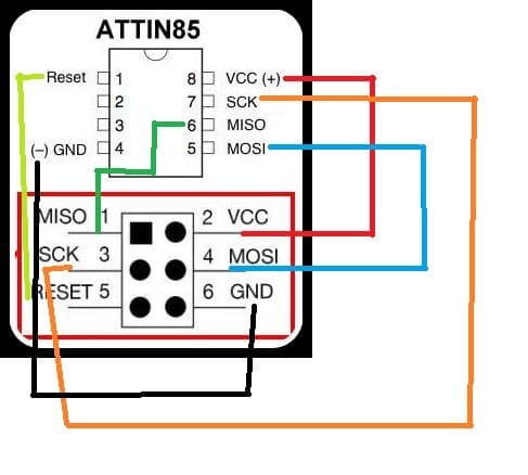
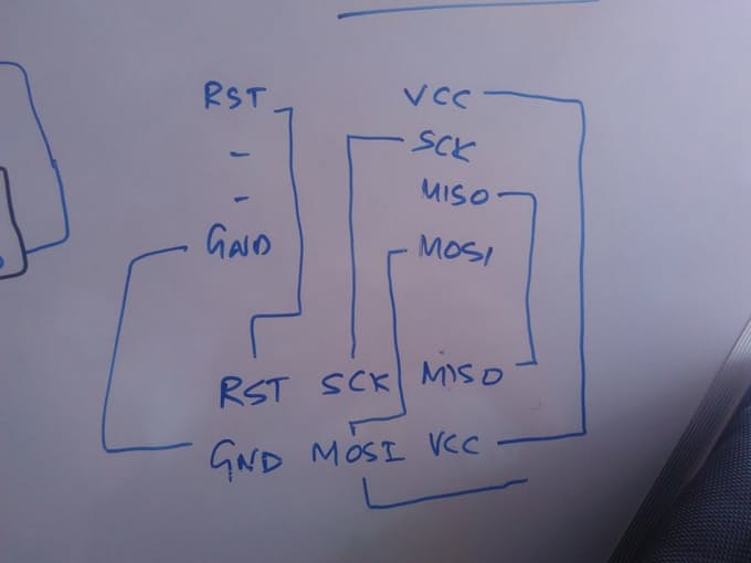
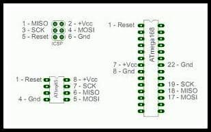
Step 4: Circuit DiagramThis circuit is to connect ATtiny and USBasp programmer to program ATtiny85 using Arduino IDE.
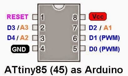
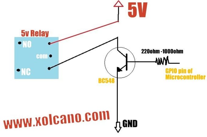
- ATtiny85 DIGITAL PIN 3 ------------ Relay through transistor (I used jumper to connect transistor base and male header)
- ATtiny85 DIGITAL PIN 4 ------------ LED
- ATtiny85 DIGITAL PIN 1 ----- NOT CONNECTED || MISO
- ATtiny85 DIGITAL PIN 0 ------ NOT CONNECTED || MOSI
- ATtiny85 DIGITAL PIN 2 ----- NOT CONNECTED || SCK
- ATtiny85 DIGITAL PIN 5 ----- NOT CONNECTED || RESET
Refer the Circuit Diagram above to make Relay circuit. Though the GPIO pins are connected to ICSP pins it can also connect to male header pins, you must Refer ATtiny tutorial by AXR AMAR for programming tutorial!
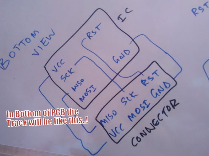
Step 5: How to Design PCB without using any Computer Software?Its okay! If you don't have any idea of designing PCB, just follow these steps to build your own.
- STEP 1 - Place the component on the Top side of the PCB and Mark using CD marker were you need to make a hole.
- STEP 2 - Drill the Hole using PCB Driller with 0.8 - 1 mm Drill Bit.
- STEP 3 - Insert your component and check whether it is perfectly drilled or not.
NOTE: Before sketching the PCB, draw it on paper and recheck again and again. If you think it is perfect then go ahead.
Step 6: Preparing Ferrous Chloride Solution!To prepare the solution you will need following items:
- water
- ferrous chloride powder
- plastic bowl
Just put some water and powder in a bowl and stir it for 1 min using any plastic spoon.
Step 7: Etching Process!Dip the copper clad board on ferrous chloride solution. Now leave it for 20 min, afterward take it out and wash it with water carefully and scrub it with sandpaper. Now the PCB is ready.
Note: You may refer to my tutorial on PCB etching.
Step 8: Soldering!Place all the components on their respective places and solder it!
Step 9: Bootloading and Programming ATtiny85!- Open the preferences dialog in the Arduino software. Find the “Additional Boards Manager URLs” field near the bottom of the dialog.
- Paste the following URL into the field (use a comma to separate it from any URLs you’ve already added):
https://raw.githubusercontent.com/damellis/attiny/ide-1.6.x-boards-manager/package_damellis_attiny_index.json
- Click the OK button to save your updated preferences.
- Open the boards manager in the “Tools > Board” menu.
- Scroll to the bottom of the list; you should see an entry for “ATtiny”.
- Click on the ATtiny entry. An install button should appear. Click the install button.
- The word install would appear on the screen. Now your Arduino IDE is ready to program your ATtiny!
For further steps go to my tutorial.
Once connection is complete and support package is installed, now you can upload the bootloader program to your tiny85. For that follow these steps:
- Go to “Tools > Board”
- Menu > Select ATtiny
- Select > Processor as ATtiny
- Go to Tools > Select programmer as "USBasp then click "Burn Bootloader"
void setup() {  // initialize digital pin 3 as an output.
  pinMode(3, OUTPUT);
}
// the loop function runs over and over again forever
void loop() {
  digitalWrite(3, HIGH);   // turn the LED on (HIGH is the voltage level)
  delay(1000);              // wait for a second
  digitalWrite(3, LOW);    // turn the LED off by making the voltage LOW
  delay(1000);              // wait for a second
}
<p>#include <SoftwareSerial.h></p>
SoftwareSerial aXr(1, 2); // RX, TX
int ledpin=3;
int BluetoothData; // the data given from Computer
void setup() {
  // put your setup code here, to run once:
  aXr.begin(9600);
  aXr.println(" press 1 or 0..");
  pinMode(ledpin,OUTPUT);
}
void loop() {
  // put your main code here, to run repeatedly:
   if (aXr.available()){
BluetoothData=aXr.read();
   if(BluetoothData=='1'){   // if number 1 pressed ....
   digitalWrite(ledpin,1);
   aXr.println("Lamp ON ! ");
   }
  if (BluetoothData=='2'){// if number 2 pressed ....
  digitalWrite(ledpin,0);
   aXr.println("Lamp Off ! ");
  }
}
delay(100);// prepare for next data ...
}
You can design your own app using app inventor.
http://appinventor.mit.edu/explore/
I have added both project file and APK file, you can either directly use my app or can edit if you need. Use UP_ARROW (serial receive 1) and LEFT_ARROW (serial receive 2) button to control relay in this project.
Instead of using DIP, we can Use SMD components. We can add I2C sensors, displays for projects, etc.
Thank you!







_3u05Tpwasz.png?auto=compress%2Cformat&w=40&h=40&fit=fillmax&bg=fff&dpr=2)
Comments