The development of terrestrial locomotion of legged robots has been continuously growing over the past few decades irrespective of the complexities involved in the design and development of these robots. This is because of the advantages in terms of maneuverability, transverse ability, ability to navigate on different terrains, efficiency, navigation over obstacles etc they have over wheel robot vehicles. The advantages of legged locomotion depend on the postures, the number of legs, and the functionality of the leg.
The quadruped robots are the best choice among all legged robots related to mobility and stability of locomotion. The four legs of the robot can be easily controlled, designed, and maintained as compared to two or six legs.
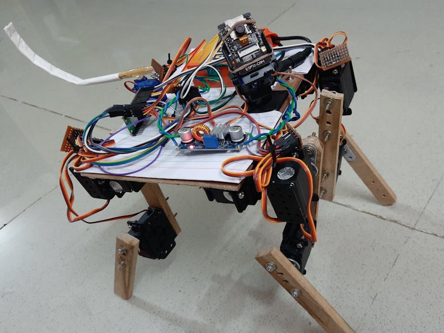
This example project demonstrates how to build a basic 4-legged WiFi remote controlled mobile robot with an on-board auto face tracking camera from scratch. It is completely controlled by the user manually from host PC through WiFi with following features
- Forward, backward, left and right walking
- Left and right rotation along its center
- Takes left and right turn while moving forward and backward
- Camera manual pan and tilt control along with flash LED
- Camera auto face tracking when a human face is detected
- Wiggle its tail when a human face is detected by the camera
Step 1: Build the hardware as described in the ‘Hardware Development’ section.
Step 2: Install latest version of CASP from this link: https://aadhuniklabs.com/?page_id=550. Please go through this link: https://aadhuniklabs.com/?page_id=554 for video tutorials on CASP.
Step 3: Download the example project on ‘4-Legged Mobile Robot with on-board Face Tracking Camera’ at this link: https://aadhuniklabs.com/casp/casp_web_projects/robotics/04_four_leg_robot.zip and follow the steps mentioned in the ‘Software Development’ section.
Step 4: Some adjustments as described in ‘Adjustments’ section are required for tuning the software to match your developed hardware. You may also further enhance the performance and features of the robot by modifying the source code from the custom blocks.
Step 5: Keyboard and mouse controls to control the robot are described in ‘Control Methodology’ section.
Step 6: Finally, safety precautions to be followed are described in 'Safety' section.
Basic Concepts of Development1) Leg Axes
The mobile robot has 4 legs named as left front, left rear, right front and right rear. Each leg is considered as a 4 axis robotic arm. From the below figures, it can be evident that Axis-1 moves the leg along X direction (side ward movement) and Axes-2 & 3 moves the leg along Y direction (forward & backward movement). Axis-4 is the end effector that touches the ground. By controlling the angles of the servos mounted at each axis, the end effector can be moved to any desired co-ordinates along X, Y, Z within its range. Alternatively, we specify the X, Y, Z co-ordinates of the end effector of each leg based on gait generation and corresponding axes angles are calculated by applying forward and inverse kinematics.
2) Gait Generation
The below figure shows the path to be followed by the end effector of each leg. Polar co-ordinates are indicated with magnitude and angle specified for each point with respect to origin (Point-B). The corresponding array created in the software is also shown.
For a standing posture all four end effectors are at Point-B. The left front leg end effector is taken as reference for all walking and rotation movements. For most of the movements, the left front leg end effector path traversal starts from Point-B through Point-C, Point-D, Point-A, and back to Point-B. This completes one gait cycle. The right rear end effector path is same as the left front leg. The other two end effectors (left rear and right front) paths are offset by 180deg. That is, they path starts from Point-D, through Point-A, Point-B, Point-C and ends at Point-D to complete a gait cycle.The robot motion is taken into consideration for arriving at the target co-ordinates (X, Y, Z) of the end effectors as explained below.
- For a forward motion the polar co-ordinates are converted to X, Y, Z along Y, Z direction with +Y pointing towards robot front.
- For backward motion, this mapped co-ordinates along Y, Z direction are rotated in X, Y direction to 180deg.
- For left right rotation, the mapped co-ordinates are rotated to +90deg or -90deg along X, Y direction depending on the rotation of the leg.
Below animation shows the path for various movements.
Once the end effector target point is calculated for a leg, its axes angles are calculated by applying forward and inverse kinematics.
3) Face Recognition/Tracking and Tail Wiggling
The mobile robot has an on-board camera with pan and tilt control. The software tries to recognize front human face during runtime. On detection, it generates a suitable signal to the servo that drives the robot tail to wiggle. Also, the software auto tracks the human face with the camera using two PID controllers and generates control signals that drive the pan and tilt servos of the camera. The two PID controllers one for horizontal tacking and the other for vertical tracking are tuned to align with the object to the center.
Hardware DevelopmentUser can build and assemble the mobile robot platform (i.e. chassis, legs etc) as shown in above pictures.
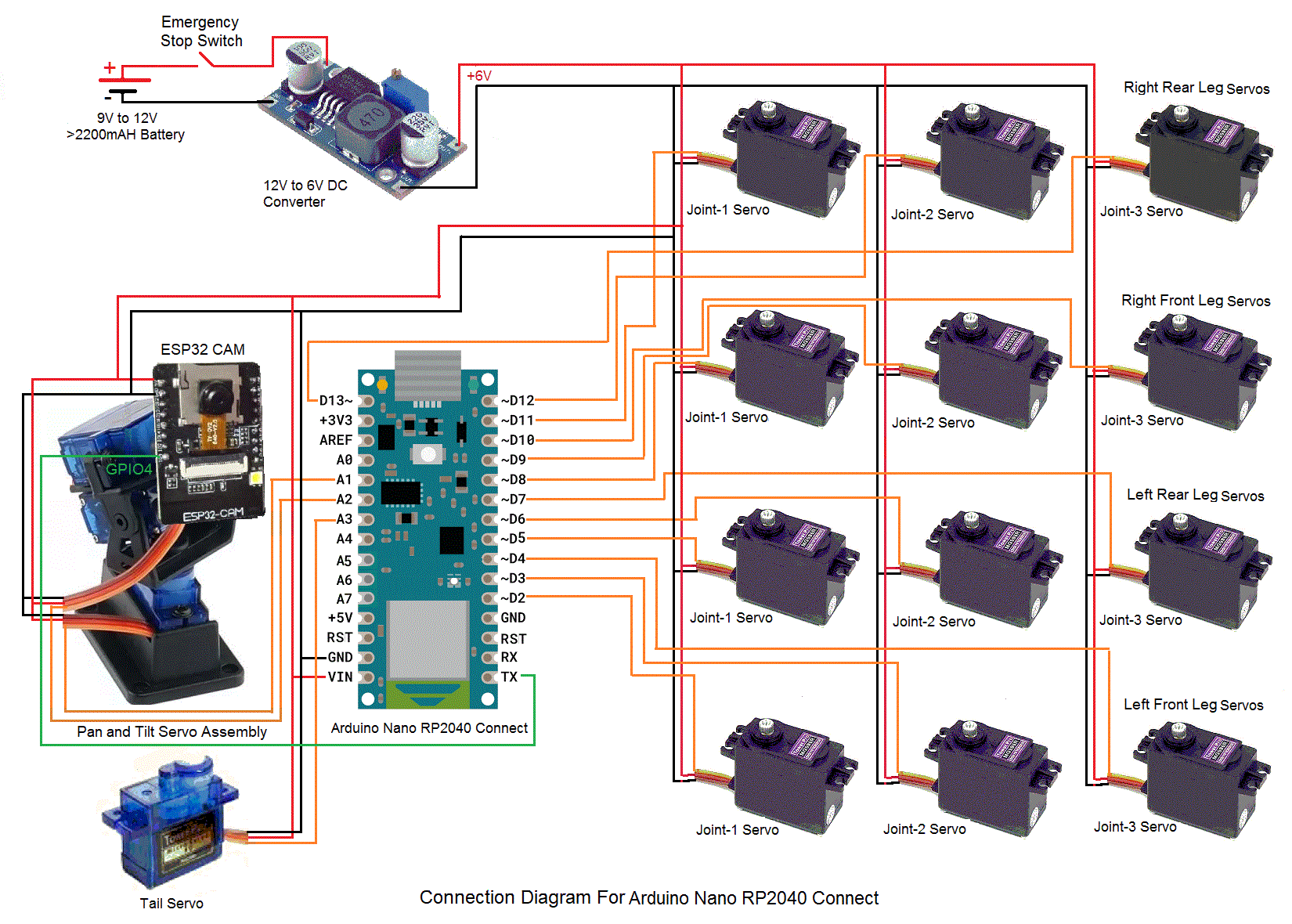
Arduino Nano RP2040 Connect and Raspberry Pi Pico W micro controller boards are independently used as the main controller of the robot. Connection diagram for both the micro controller boards are shown below. They control all the movements of the robot and communicates with the host PC through on-board WiFi.
The micro controller generates required PWM signals to control the leg servos. It also controls the servos of the camera pan & tilt assembly and tail wiggle assembly.
An ESP32 Camera module is mounted on the pan & tilt assembly for capturing live video and stream to the host PC.
A 12V battery with minimum 2200mAH capacity along with a 12V to 6V DC step down converter is used to power the entire circuitry on the robot.
Suitable high torque servo motors are used for robotic leg axes rotation.
Required electronic modules are suitably placed on the base frame and are connected as per the connection diagram shown in ‘Schematic’ section'.
Software DevelopmentA) Configuring ESP32 Camera
ESP32 Camera shall be properly programmed with valid IP address before using it in the project. Please refer to our ESP32-CAM example for details on how to program the module. User may also refer to abundant material available on the internet regarding this subject.
B) Software for micro-controllers and host PC
CASP software is used to quickly create models and generate binary code for the on-board micro-controller target and native PC. This software enable users to graphically visualize the signal at any point of the model in real time. This feature is extensively used during adjusting robotic arm joint block parameters.Two models are developed to achieve desired objective.
B.1) Target Model that runs on Arduino Nano RP2040 Connect and Raspberry Pi Pico W consists of
1) Blink logic that indicates the system is running.2) WiFi101 block that receives required control signals from host PC.3) PWM and servo blocks that are mapped to the pins of the micro-controller.
Following are the steps to properly program the target board.
1) Connect the target to the host PC via a USB cable and note the serial port number from the host operating system.
2) Run CASP and load project ‘rc_arduino’ for Arduino RP2040 target or ‘rc_pico’ for Raspberry Pi Pico W target.
3) The WiFi101 block WiFi is set to Station mode. User may need to enter SSID and password of the network to which the device should be connected. The Local IP address parameter shall be configured as assigned by the network DHCP client of the network.
4) Open Home->Simulation->Setup Simulation Parameters menu item. Under TargetHW->General tabs set ‘Target Hardware Programmer Port’ parameter to the serial port to which the board is connected.
5) Build the model and program the board by clicking on Run button.
B.2) Native Model that runs on Host PC consists of
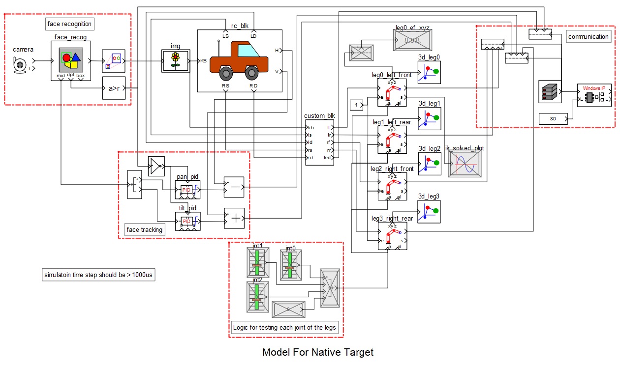
1) Face recognition logic consists of camera block and face recognition block. Camera block receives live video from the ESP32 Camera mounted on the mobile robot. IP address of the ESP32 Camera shall be entered in block parameters of this block.
2) Image display block (img) to display the live video received from the camera. It is also configured to output keyboard and mouse signals.
3) RC control block (rc_blk): It is a custom block that receives keyboard and mouse signals from the image display block and generates suitable control signals for controlling the robot motion. User can take a look at the configuration and source code of the block to better understand the logic and learn how to integrate the block in a CASP model along with other blocks. User can go through our video tutorial on how to create a custom block at this link https://aadhuniklabs.com/casp_res_videos#custom_block.
4) Robotic leg control block (custom_blk) embeds complete source code for proper gait generation and calculate XYZ co-ordinates for each leg end effector based on the control signals received from the’ rc_blk’. As it is a custom block, user can take a look at the configuration and source code of the block to better understand the logic.
5) Robotic leg axes blocks (4 number) takes input from the ‘custom_blk’ and calculates servo angles for each axis. It calculates forward and inverse kinematics for generating required axes angles to control the servo motors. The parameters of these blocks are configured to match with the respective leg segment dimensions/parameters.
6) 3D view blocks (4 numbers) attached to each leg block are used to plot each axis coordinates (as shown in below screen short). These can be used during testing for proper gait generation before connecting to the hardware.
7) WiFi communication block for communicating with the target hardware on the mobile robot.
Following are the steps to run the native model on the host PC
1) Before continuing, the host PC shall be connected to the same network as the device is connected.
2) Load the ‘rc_native’ project.
3) Click on Home->Simulation->Configure Simulation IO menu item.
4) ‘Configure Simulation Hardware’ window will open. Under Native Nodes and GPIO Device Nodes, change the IP addresses marked in the below figure (by double clicking on the item) to respective local and device IP addresses.
5) Click on ‘Connect Device’ button and check the ‘Online Data’ check box. The program should now communicate with the target with cycle time around 20msecs. Target board is now available as end point ‘EP0’ to the native model. Native model can use this end point to connect to respective IOs on the target.
6) After successful communication, user may need to enter a dummy address in the local IP and ensure that no communication happen during run time through this method as we don’t use this method for communicating with the target. We only use this method during testing.
7) Click on ‘Save’ button to save the configuration and close the window.
8) Now, configure the local and target IP addresses in the ‘Windows IP’ block from the model. These IP addresses shall be same as the addresses that worked while communicating to the target using the above method. A screen shot of the ‘Windows IP’ block parameter is shown below. Such communication methodology is chosen to reduce number of block count in the model.
9) Run the model by clicking on the Run button. A simulation panel window should open and communicate with the board.
10) Screen shot of the output simulation panel running on host PC is shown below. On some systems where graphics hardware cannot display the 3D plot correctly, user is advised to disable the 3D block.
1) The individual leg axes angle range and offset is set for each servo block in the target model based on the servo placement and alignment as shown in below figure. In the below figure each axis servo angle range (between -90deg to +90deg) with 0deg angle direction is shown. The polarities shown are indicative and vary for each leg based on the alignment of the servos. If user finds some mismatch in his/her design then it can be adjusted in the ‘Input Offset’ parameter of the ‘servo’ blocks in the target model.
2) The Axis-1/2/3/4 Settings (such as DH Arm Length, DH Arm Offset, DH Arm Twist and DH Arm Rotation Offset) of the Robotic Arm blocks for the 4 legs in the native model shall be adjusted based on the actual robot leg parameters built by the user.
3) Four 3D view blocks attached to the four legs can be used to view the axes movement while developing/building/testing the robot.
4) Manual control of each axis of the leg is possible. For this, user may need to enable the blocks grouped under ‘Logic for testing each joint of the legs’ shown in the below figure. Currently these blocks are disabled to bring down total blocks within the Free License version limitations. User can enable these block while disabling other non-related blocks such as blocks for face recognition and face tracking temporarily. The output of the above block group is given to all four leg blocks. In the leg blocks, user may also need to set ‘Runtime Control’ parameter of each axis to ‘Angle’ to enable manual control.
5) Base speed, speed limits and other parameters related to the navigation are adjustable from the ‘rc_block block and ‘custom_blk’ parameters.
Control Methodology1) User can use keys W – to move forward, S – to move backward, A – to rotate left and D – to rotate right. Using the keys A and D along with the shift key moves the robot along left and right direction.
2) Combination of keys W/S & A/D can be used to take left and right turns while moving forward or backward.
3) Speed can be adjusted by using Page Up & Page Down keys.
4) Vertical and horizontal servo angles (from -90 to +90 deg) for head position control can be controlled by mouse movements.
5) Key ‘G’ is used to position both servos at default angle.
6) Key 'L' is used to ON/OFF the flash LED light of the ESP32 camera.
SafetyAt times the robotic legs can go out of control. One way to slow down the leg movement is to adjust the servo block parameters (in the target model) to limit the rate of change of axes angles.Take adequate precautions to avoid injuries. Keep the piece out of reach from children at least during the development stage.
ReferencesPlease go through our video tutorials, tutorial projects and CASP main documentation for getting started with CASP. Link: https://aadhuniklabs.com/casp-resources.


Comments
Please log in or sign up to comment.