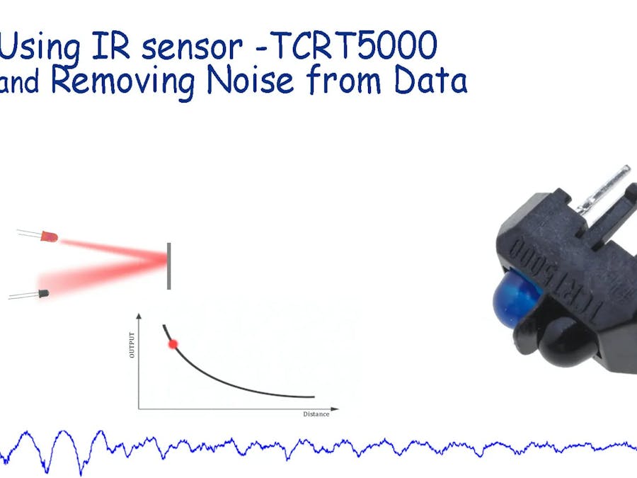
In this tutorial, basic circuitry for TCRT 5000 IR sensor and its working is discussed. This sensor is typically used to measure the rough distance of the target or for proximity purposes. These type of sensors suffers from static noise present in the environment. So a major focus of this tutorial is on making a program which enables it to remove all kind of ambient noise. So after using this method IR sensor need not be calibrated for different ambiance conditions.
Working of IR Sensor:Distance measuring is very easy using the IR sensor. A beam of IR is transmitted to the target and the reflected beam is captured by the photodiode. The photodiode measures the intensity of light (here mostly IR light). IR diode does not measure the intensity of just IR light but it is also sensitive to visible light. The Intensity of IR light recorded by photodiode represents the distance between the target and sensor.
This method is not very accurate and output is also non-linear. As mentioned earlier this method suffers a lot from ambient noise, so users need to calibrate it every time ambient condition changes.
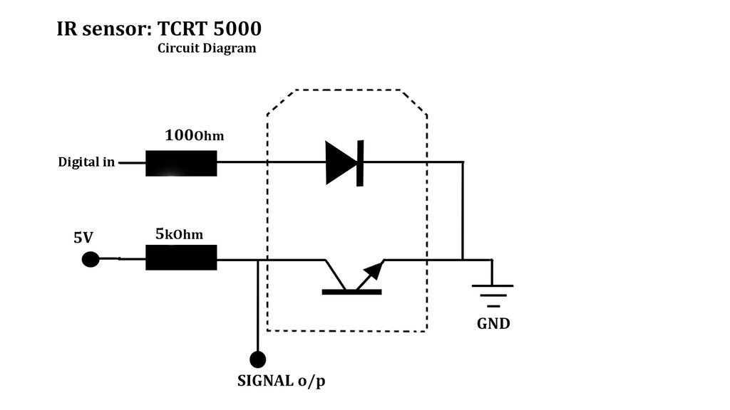
Making Circuit for Sensor:We are driving out photodiode using a basic resistor based circuit. we can also use op-amp based more accurate and better methods for precise measurement.
IR LED is connected with 100 Ohm of the resistor in series to the digital pin of Arduino. and the photodiode is connected to 5k Ohm of the resistor in series to 5v of supply and signal is taken out from it which goes to the analog input pin of Arduino.
Checking Circuit:Upload this code to Arduino.
void setup()
{
Serial.begin(9600);
pinMode(6,OUTPUT);
}
void loop()
{  digitalWrite(6,HIGH);
delayMicroseconds(500);
a=analogRead(A3);
Serial.println(a); }
Now turn ON serial plotter and move some target in front of the sensor. The plot also should move as per the movement of the target displacement.
The problem with this method:
- Measurement is ambiance sensitive. any change in light can ruin measurement.
For example, if we calibrate the sensor in the morning can not be used for the evening. And even in indoor if we turn ON - Off room light, calibration gets changed.
Sources of Noise and Solution:The changes in calibration occur due to various noise present in the environment. There are various sources of noise like:
- IR radiation from the sun: The sun transmits a huge portion of IR radiation to earth. which captured by IR photodiode and reading is no more correct.
- Indoor lighting: IR photodiode does not capture just IR light but also senses visible light transmitted by room lights.
- Heat source: All heat sources emit some sort of radiation that is captured by IR photodiode. the amount of this radiation so error depends upon the temperature and size of a body.
These sources emit IR radiation, which is captured by IR Photodiodes. so the error is added to our measurement.
Solution:As shown in the image, If we turn ON led than photodiode measures noise+signal and if led turn Off photodiode receives just noise. The difference between these two values will give denoised data. If we take two reading very fast enough denoising would get better.
Note: however, this subtraction of noise data will not give perfectly accurate output as the relation between distance and sensor output is nonlinear. However, for low accuracy applications, this should work satisfactorily.
Testing Code for Denoising and ApplicationThese pictures show RAW data, noise value, and pure signal. you can also refer to the video in which output from the sensor in presence of flashing light as well as static noise.
This approach can be used in line follower so that we do not need to calibrate sensor every time we use. It also can be used in some bots where the IR sensor is used for the same advantage.


_ztBMuBhMHo.jpg?auto=compress%2Cformat&w=48&h=48&fit=fill&bg=ffffff)


Comments
Please log in or sign up to comment.