


Hardware components | ||||||
_ztBMuBhMHo.jpg?auto=compress%2Cformat&w=48&h=48&fit=fill&bg=ffffff) |
| × | 1 | |||
 |
| × | 1 | |||
 |
| × | 1 | |||
 |
| × | 1 | |||
Software apps and online services | ||||||
 |
| |||||
A seven-segment display is a form of electronic display device for displaying decimalnumeralsthat is an alternative to the more complex dot matrix displays.
Seven-segment displays are widely used in digital clocks, electronic meters, basic calculators, and other electronic devices that display numerical information.
How does it work?Let’s briefly discuss the characteristics and functionality of the 7-segment display before we connect it to an Arduino.
The 7-segment displays are really just seven LEDs lined up in a particular pattern. In this case, the number ‘8’ shape we’re all familiar with. Each of the seven LEDs is called a segment because when illuminated the segment forms part of a numerical digit (both Decimal and Hex) to be displayed. An additional 8th LED is sometimes used for indication of a decimal point.
Each one of the seven LEDs in the display is given a positional segment with one of its connection pins being brought straight out of the rectangular plastic package. These individual LED pins are labeled from a through to g representing each individual LED. The other LED pins are connected together and wired to form a common pin.
To turn on and off a particular part of the display, you set the appropriate pin HIGH or LOW just like you would with a regular LED. So that some segments will be light and others will be dark allowing the desired character pattern of the number to be generated on the display. This then allows us to display each of the ten decimal digits 0 through to 9 on the same 7-segment display.
Seven segment types :Seven segment displays are of two types: Common Cathode (CC) and Common Anode (CA).The Internal structure of both types is nearly the same. The difference is the polarity of the LEDs and common terminal. As their name suggests, the common cathode has all the cathodes of the LEDs in a 7-segment connected together and the common anode has all the anodes of the LEDs in a 7-segment connected together.
In the common cathode display, all the cathode connections of the LED segments are connected together to ‘logic 0’ / GND. The individual segments are then illuminated by applying HIGH / ’logic 1’ signal to the individual Anode terminals (a-g).
In the common anode display, all the anode connections of the LED segments are joined together to logic “1”. The individual segments are illuminated by applying a ground, logic “0” or “LOW” signal to the Cathode of the particular segment (a-g).
You can know the type by testing it, when you connect one of the center pins from the seven segment to GND and connect one of the other pins to VCC and it turned on, that means the seven segment is common cathode, otherwise the seven segment is common anode.
How to know the pin ?You can test them by connecting the center to (GND to cathode / VCC to anode)
and any other pin to (VCC to cathode / GND to anode).
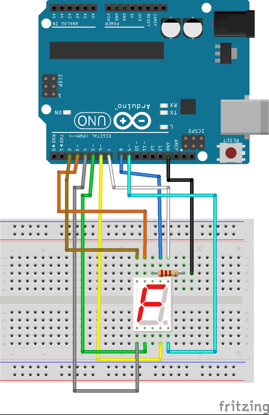
In this code tutorial, the Schematic shows the connections between the seven segment and the Arduino.
The code :/*
Showing numbers, chars and phrases
A (seg[0] in this project)
---
F (seg[5] in this project) | | B (seg[1] in this project)
| |
--- G (seg[6] in this project)
E (seg[4] in this project) | |
| | C (seg[2] in this project)
--- . dot or dicimal (seg[7] in this project)
D (seg[3] in this project)
*/
#define A 8
#define B 7
#define C 6
#define D 5
#define E 4
#define F 3
#define G 2
#define DP 9 // decimal
#define common_cathode 0
#define common_anode 1
bool segMode = common_cathode; // set this to your segment type, my segment is common_cathode
int seg[] {A,B,C,D,E,F,G,DP}; // segment pins
byte chars = 35; // max value in the array "Chars"
byte Chars[35][9] {
           {'0',1,1,1,1,1,1,0,0},//0
           {'1',0,1,1,0,0,0,0,0},//1
           {'2',1,1,0,1,1,0,1,0},//2
           {'3',1,1,1,1,0,0,1,0},//3
           {'4',0,1,1,0,0,1,1,0},//4
           {'5',1,0,1,1,0,1,1,0},//5
           {'6',1,0,1,1,1,1,1,0},//6
           {'7',1,1,1,0,0,0,0,0},//7
           {'8',1,1,1,1,1,1,1,0},//8
           {'9',1,1,1,1,0,1,1,0},//9
           {'a',1,1,1,0,1,1,1,0},//A/10
           {'b',0,0,1,1,1,1,1,0},//b/11
           {'c',1,0,0,1,1,1,0,0},//C/12
           {'d',0,1,1,1,1,0,1,0},//d/13
           {'e',1,0,0,1,1,1,1,0},//E/14
           {'f',1,0,0,0,1,1,1,0},//F/15
           {'g',1,0,1,1,1,1,0,0},//G/16
           {'h',0,1,1,0,1,1,1,0},//H/17
           {'i',0,0,0,0,1,1,0,0},//I/18
           {'j',0,1,1,1,1,0,0,0},//J/19
           {'l',0,0,0,1,1,1,0,0},//L/20
           {'n',0,0,1,0,1,0,1,0},//n/21
           {'o',0,0,1,1,1,0,1,0},//o/22
           {'p',1,1,0,0,1,1,1,0},//P/23
           {'q',1,1,1,0,0,1,1,0},//q/24
           {'r',0,0,0,0,1,0,1,0},//r/25
           {'s',1,0,1,1,0,1,1,0},//S/26   looks like number 5
           {'t',0,0,0,1,1,1,1,0},//t/27
           {'u',0,1,1,1,1,1,0,0},//U/28
           {'y',0,1,1,1,0,1,1,0},//y/29
           {'-',0,0,0,0,0,0,1,0},//-/30
           {'.',0,0,0,0,0,0,0,1},//./31
           {']',1,1,1,1,0,0,0,0},//]/32
           {'[',1,0,0,1,1,1,0,0},//[/33
           {'_',0,0,0,1,0,0,0,0},//_/34
           };
void setup() {
 // set segment pins as OUTPUT
pinMode(seg[0],OUTPUT);
pinMode(seg[1],OUTPUT);
pinMode(seg[2],OUTPUT);
pinMode(seg[3],OUTPUT);
pinMode(seg[4],OUTPUT);
pinMode(seg[5],OUTPUT);
pinMode(seg[6],OUTPUT);
pinMode(seg[7],OUTPUT);
}
void setState(bool mode) //sets the hole segment state to "mode"
{ for(int i = 0;i<=6;i++)
{
digitalWrite(seg[i],mode);
}
}
void Print(char Char) // print any character on the segment ( Note : you can't use capital characters )
{
int charNum = -1;// set search resault to -1
setState(segMode);//turn off the segment
for(int i = 0; i < chars ;i++){//search for the enterd character
if(Char == Chars[i][0]){//if the character found
charNum = i;//set the resault number into charNum ( because this function prints the character using it's number in the array )
}
}
if(charNum == -1 )// if the character not found
{
for(int i = 0;i <= 6;i++)
{
digitalWrite(seg[i],HIGH);
delay(100);
digitalWrite(seg[i],LOW);
}
for(int i = 0;i <= 2;i++)
{
delay(100);
setState(HIGH);
delay(100);
setState(LOW);
}
}else // else if the character found print it
{
for(int i = 0;i<8;i++)
{digitalWrite(seg[i],Chars[charNum][i+1]);
}
}
}
void Print(int num) // print any number on the segment
{
setState(segMode);//turn off the segment
if(num > chars || num < 0 )// if the number is not declared
{
for(int i = 0;i <= 6;i++)
{
digitalWrite(seg[i],HIGH);
delay(100);
digitalWrite(seg[i],LOW);
}
for(int i = 0;i <= 2;i++)
{
delay(100);
setState(HIGH);
delay(100);
setState(LOW);
}
}else // else if the number declared, print it
{
if(segMode == 0){ //for segment mode
for(int i = 0;i<8;i++)
{digitalWrite(seg[i],Chars[num][i+1]);
}
}
else{
for(int i = 0;i<8;i++)
{digitalWrite(seg[i],!Chars[num][i+1]);
}
}
}
}
void loop() {
 for(int i = 0;i < chars;i++) //print
 {
   Print(i);
  delay(1000);
 }
//Print(number or character); // print any number or character on the segment ( Note : you can't use capital characters )
//setState(state); //sets the hole segment state to "mode"
}
#define A 8
#define B 7
#define C 6
#define D 5
#define E 4
#define F 3
#define G 2
#define DP 9 // decimal
Those are pin defines.
#define common_cathode 0
#define common_anode 1
Seven segment types define.
bool segMode = common_cathode;
Seven segment type, set to your seven segment type.
int seg[] {A,B,C,D,E,F,G,DP}; // segment pins
Put the pins in an array, ( IMPORTANT:don'tdeletethisarraybecauseit'susedinthecode)
byte chars = 35; // max value in the array "Chars"
Set this to the number of the characters in "Chars"(IMPORTANT:thisvariableisusedinthecode)
byte Chars[35][9] {
{'0',1,1,1,1,1,1,0,0},//0
{'1',0,1,1,0,0,0,0,0},//1
{'2',1,1,0,1,1,0,1,0},//2
{'3',1,1,1,1,0,0,1,0},//3
{'4',0,1,1,0,0,1,1,0},//4
{'5',1,0,1,1,0,1,1,0},//5
{'6',1,0,1,1,1,1,1,0},//6
{'7',1,1,1,0,0,0,0,0},//7
{'8',1,1,1,1,1,1,1,0},//8
{'9',1,1,1,1,0,1,1,0},//9
{'a',1,1,1,0,1,1,1,0},//A/10
{'b',0,0,1,1,1,1,1,0},//b/11
{'c',1,0,0,1,1,1,0,0},//C/12
{'d',0,1,1,1,1,0,1,0},//d/13
{'e',1,0,0,1,1,1,1,0},//E/14
{'f',1,0,0,0,1,1,1,0},//F/15
{'g',1,0,1,1,1,1,0,0},//G/16
{'h',0,1,1,0,1,1,1,0},//H/17
{'i',0,0,0,0,1,1,0,0},//I/18
{'j',0,1,1,1,1,0,0,0},//J/19
{'l',0,0,0,1,1,1,0,0},//L/20
{'n',0,0,1,0,1,0,1,0},//n/21
{'o',0,0,1,1,1,0,1,0},//o/22
{'p',1,1,0,0,1,1,1,0},//P/23
{'q',1,1,1,0,0,1,1,0},//q/24
{'r',0,0,0,0,1,0,1,0},//r/25
{'s',1,0,1,1,0,1,1,0},//S/26 looks like number 5
{'t',0,0,0,1,1,1,1,0},//t/27
{'u',0,1,1,1,1,1,0,0},//U/28
{'y',0,1,1,1,0,1,1,0},//y/29
{'-',0,0,0,0,0,0,1,0},//-/30
{'.',0,0,0,0,0,0,0,1},//./31
{']',1,1,1,1,0,0,0,0},//]/32
{'[',1,0,0,1,1,1,0,0},//[/33
{'_',0,0,0,1,0,0,0,0},//_/34
};
This is the character list, this project uses the first characters to show it, the 0/1 values are the states of every pin of "seg[]".
void setup() {
// set segment pins as OUTPUT
pinMode(seg[0],OUTPUT);
pinMode(seg[1],OUTPUT);
pinMode(seg[2],OUTPUT);
pinMode(seg[3],OUTPUT);
pinMode(seg[4],OUTPUT);
pinMode(seg[5],OUTPUT);
pinMode(seg[6],OUTPUT);
pinMode(seg[7],OUTPUT);
}
Those are " pinModes ".
Those are the important explanations for the user of this project.
The functions :This project contains two helpful functions, let's learn how to use them!
Print(number or character)This function used to print characters or numbers on the seven segment!
You can use it like Print(number or character) but in a char value, and you can use it like Print(number of the character in array "Chars") and hole seven segmentthis way uses only the number of the character in array " Chars ".
Examples:
1:
for(int i = 0;i < chars;i++) //print
{
Print(i);
delay(1000);
}
This is the second way for printing, I made this way to be easy to use with the for loops and other stuff.
2:
Print('y');// or any other character
And this is the first way for printing.
setState(state)This function sets the hole seven segment to HIGH or LOW "state".

Comments
Please log in or sign up to comment.