
Hardware components | ||||||
 |
| × | 1 | |||
 |
| × | 1 | |||
Software apps and online services | ||||||
 |
| |||||
| ||||||
| ||||||
Hand tools and fabrication machines | ||||||
 |
| |||||
 |
| |||||
When I was a sweet little boy, I wanted to play video games. The devices were not expensive where I grew up; we just didn't have the money. I took the bus to the Flea Market and bought the cheapest secondhand gaming console I could find. I used an adapter that we had at home to power it up, but it showed no sign of life. Spent some time troubleshooting and found that the power barrel jack was broken. I soldered it in place then wasted many hours playing on that thing.
Game PlanFastforward couple of decades, I stumbled upon a good deal at AliExpress. I was planning on hacking the wireless transmission, but that might take some time. I couldn't find an easy way to hack I2C like I did in Non-contact Infrared Thermometer Readings In Google Sheets or UART like I did in The AVR-IoT WG: Out for Blood Pressure Monitoring in Google. So, I decided to go medieval on the controller.
The idea here is to use a microcontroller to control the gaming console controller.
HardwareI bet you can't tell which controller I damaged. Trick question: the answer is "both". Started with the controller on the right but ended up stripping a solder pad and a trace, and breaking the board in half (still works). I've had more success with the second controller only because I used copious amounts of superglue and baking soda.
Luckly, it does not matter which controller to use because the console will treat the first one it finds as the main one.
ESP01S plugs into the controller PCB via the white 8 pin connector, but we're only using 6: 3.3V, GND, Down, A button, Start, and Select.
Yes, we're using 2 x 1.5V AAA batteries to provide power to 3.3V ESP01S, but that is not an issue on fresh batteries. However, we need to find a more suitable power supply for this project past the prototyping stage.
SoftwareIn this project, ESP01S will act as a Wi-Fi Access Point and a server while M5Stack Core2 will be the client. To keep the ESP01S and M5Stack Core2 code together, I created two entries in platformio.ini:
[env:esp01_1m]
.
.
.

[env:m5stack-core2]
.
.
.
In main.cpp, I used the following directives to make both codes coexist in the same file:
#if defined(ARDUINO_ESP8266_ESP01)
.
.
.

#elif defined(ARDUINO_M5STACK_Core2)
.
.
.

#else
#error Unsupported board selection.
#endif
I did mention that method in previous projects, but never explained where I obtained defines from. Simple, they are all in c_cpp_properties.json.
In order to convert Tx and Rx pins of ESP01S to GPIO pins we need to do the following:
pinMode(i, FUNCTION_3);As a server, ESP01S expects two values separated by a comma and they represent how many times to press the down button and how many times to press A button via a POST request. Before we press any buttons we need to reset the console to start from a known state by holding down both Start and Select at the same time (RTFM save me many trips to the console!). Finally, ESP01S presses Start to select the game.
M5Stack Core2 has 2 screens that we can switch between them by swiping left or right:
- Number Pad AKA Screen 0: We need to enter a number between 1 and 620 to start a specific game by tapping on the resulting number on the top. Found an out-of-date example Simple Touch Keyboard | M5Stack Communit and modified it to make it work with the latest release of M5Core2.h.
- Speed Dial AKA Screen 1: Here we can select one of four games with a single tap. Used a free online File to hexadecimal converter to save the speed dial images in a format that can be efficiently used by M5Stack Core2. This code is saved in images.h file. Behind each image we have a button that is programmed to send a specific number of down and A buttons to ESP01S.We can add more Speed Dial screens if needed.
Uploading the code to M5Stack Core2 was straightforward via a USB-C cable. To upload code to ESP01S, checkout Tracking Space Stations With RT-Thread Studio - Hackster.io.
Demo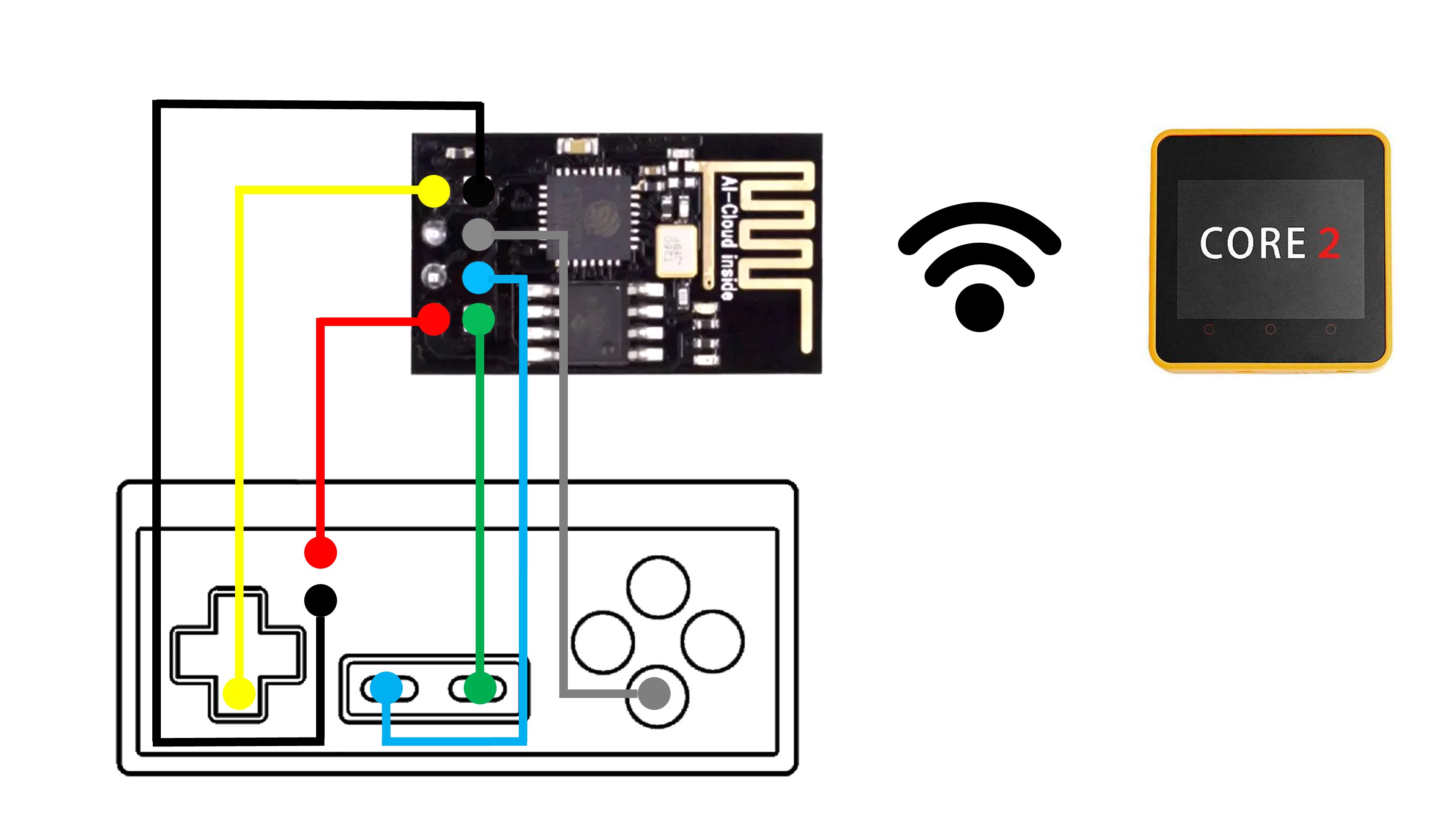


Comments