
_ng6xGzwt4h.gif?auto=format%2Ccompress&gifq=35&w=400&h=300&fit=min)

Hardware components | ||||||
| × | 1 | ||||
 |
| × | 1 | |||
 |
| × | 1 | |||
Software apps and online services | ||||||
 |
| |||||
| ||||||
| ||||||
| ||||||
| ||||||
Hand tools and fabrication machines | ||||||
 |
| |||||
 |
| |||||
Many of my fellow makers used Single Board Computers (SBC) and paid Application Programming Interface (API) to tack satellites orbiting the Earth. This project is a simple and low cost method to track Space Stations. We used knowledge gained from my previous project and data provided to our web browser for free by n2yo.com. Furthermore, we displayed the names of people currently in space using information gathered by open-notify.org.
Game PlanJust like in the previous project, we used UART to communicate between STM32F469 DISCOVERY board and the Wi-Fi Dev board. To add an extra challenge and reduce the cost of implementation we replaced ESP32 with ESP-01 which required a programmer because there is no USB port.
We got the URLs we needed to use by pressing F12 on the page we need to get data from. Studying JavaScrips revealed that we have to use the following format:
https://www.n2yo.com/sat/instant-tracking.php?s=<NORAD ID>&d=1The North American Aerospace Defense (NORAD) ID is 25544 for ISS and for Tiangong it is 48274. Making a GET request to the URL above will return a JSON formatted string that contains the GPS coordinates to be displayed. That string and the one received from http://api.open-notify.org/astros.json are so simple we didn't have to use a library to parse them.
Board Support Package (BSP)We started by downloading and extracting https://github.com/RT-Thread/rt-thread/archive/refs/heads/master.zip to get the latest BSP. According to the User Manual, we have four USART ports and, four UART ports on that board, however, only USART3 is enabled by default. Using STM32 CubeMX, we opened %userprofile%\Downloads\rt-thread-master\rt-thread-master\bsp\stm32\stm32f469-st-disco\board\CubeMX_Config\CubeMX_Config.ioc
After clicking Continue, we expanded connectivity on the left pane and clicked USART6.
We replaced Disabled with Asynchronous in the Mode drop down menu. We then clicked Generate Code in the top right corner and closed the the application.
We located Kconfig (one folder up) and duplicated UART3 text then replaced with UART6. Now, it looks like this.
BSP is ready to be used after saving this file.
RT-Thread StudioOne minute into this tutorial shows how to import BSP that we just modified.
This is how our import looked.
We opened RT-Thread Settings from the left pane then clicked on the chevrons on the right.
We came here to Enable LVGL for LCD which will automatically trigger all the needed toggles.
We needed to also turn on UART6 we just enabled.
We had to increase Rx buffer size from 64 to 1024.
We deleted all files in applications folder then copied our files from Github.
To allow auto reset after code download we needed to make this change.
Please note that this tutorial is using LVGL v8.3.1 and if you have to look something up on their website, make sure you are looking at the correct version.
We used tzapu/WiFiManager to connect ESP-01 to Wi-Fi without hard coding credentials. Once we are online we can wait for URL to come from STM32F469 DISCOVERY via UART then send back the unprocessed response.
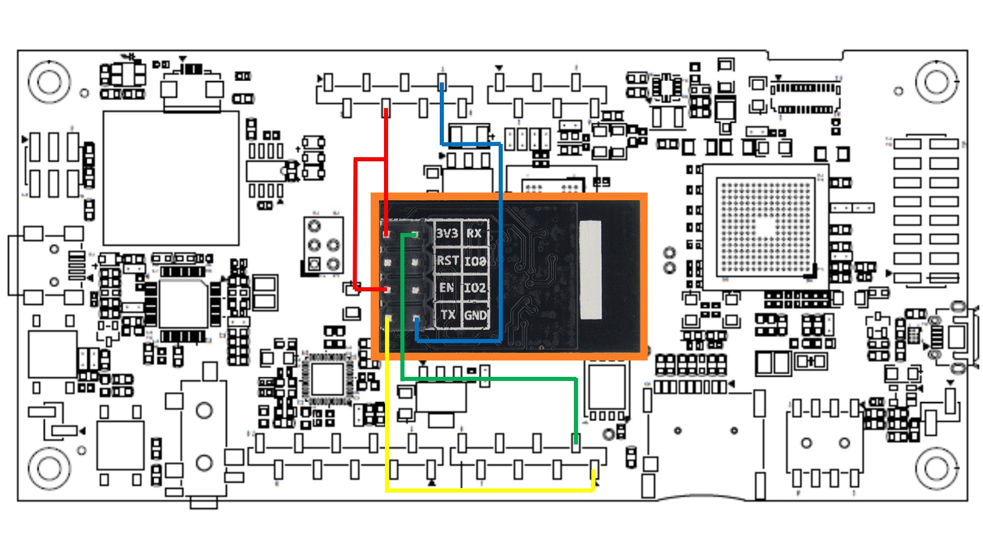
HardwareWe used the standard UART connection to make the boards communicate. Tx of one board is connected to Rx of the other and vice versa. We are powering STM32F469 DISCOVERY with USB cable, and powering ESP-01 from it.
The breakout board we bought from AliExpress had one small problem; see if you can spot it.
Luckily the swapped pins didn't cause permanent damage to the programmer or ESP-01.
We soldered two switches on the bottom of the breakout board then connected it to a USB Serial Adapter. One switch is the reset switch that connects RST to ground. The second switch keeps GPIO0 grounded while resetting the board then it can be release right after that.
Before we plug to the laptop we ensured the programmer's jumper is on 3.3V position not 5V. We used VS Code to program ESP-01, but Arduino IDE could be used, too. The red jumper between Vcc and CHPD is needed regardless of the mode.


Comments
Please log in or sign up to comment.