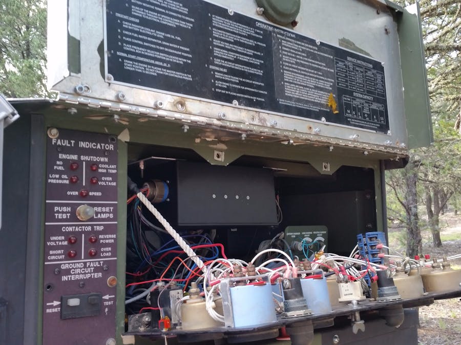
This project involves monitoring and control of a micro-grid, consisting of a photo-voltaic (PV) array (solar panels), a battery bank for storage and a diesel generator to supplement power during dark or cloudy conditions. This project specifically targets the monitoring and control of the diesel generator. The specific generator is an Army/Air Force PU-801 trailered 15 kW generator. The generator manual is documented at http://www.liberatedmanuals.com/TM-9-6115-661-13-and-P.pdf. The project monitors up to 8 analog values from the generator. These values include fuel level, oil pressure, coolant temperature, system voltage, DC charge/discharge current, AC voltage, AC current and AC frequency. Control includes sequencing of the ignition switch, the fault clear switch and the AC interrupter switch.
The monitoring is fairly trivial using an MCP3008 10-bit ADC, isolated with unity gain op-amp buffers with voltage dividers on the inputs. Control is done using a relay driver IC. Pretty simple circuitry.
The real trick is the sequencing and timing of the control. First, depending on ambient temperature, preheat is applied. Then, the fuel pump is activated for a duration. Then, the starter is activated until oil pressure reaches a certain level and then disengaged. If oil pressure does not reach the determined level within a determined duration, another duration is waited before trying again, to let the starter cool down. This cycle is repeated x number of times before giving up. Then, the fault indicator panel always indicates a low voltage fault, which must be cleared using a relay. Then, after a duration, the AC interrupter switch must be activated to allow the AC voltage output of the generator to be enabled.
The trick here is to allow manual operation and automated operation. That is, a human operator can physically start and enable AC voltage and allow the control system to do the same. This is a little tricky. I have done this successfully, but will only supply the circuitry and software upon IP agreement (I'm not giving that part away for free).
Additional rules determine when to attempt to start the generator depending on the battery bank voltage level and the generator battery level.
The system may be monitored and controlled locally and remotely using wired or wireless connectivity. This project adds the ability to monitor and control the generator using cellular connectivity.
I provide the schematics and rudimentary software for monitoring of the analog values and control of the relays. Detailed control and wiring are my IP and you may contact me to learn more.
Relevant Raspberry Pi libraries are:
https://learn.adafruit.com/raspberry-pi-analog-to-digital-converters/mcp3008
https://pypi.python.org/pypi/RPi.GPIO


Comments
Please log in or sign up to comment.