One of the great things about the SP701 is from AMD is there is a reference design which can be used to quickly create an image processing system using the PCAM5C camera and a HDMI or DSI display.
We learned how to do this in a previous project here
In this project we are going to use the same reference design and add in a custom IP block which we have created using MATLAB Simulink and the HDL coder.
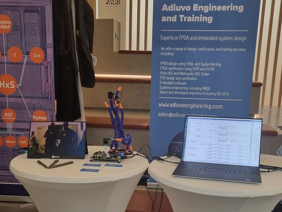
If you attended the FPGAWorld show in Sweden in September 2022 you may have also seen this example running on our stand. It attracted a lot of interest so I thought it would make a good project for Hackster explaining how we did it.
As I mentioned the design for the auto white balance block was created in MATLAB and Simulink using HDL Coder. HDL coder enables us to generate HDL files which can be implemented in our target FPGA as a IP block.
The AWB IP design is intended to sum up the 2 pixels per clock, received for the RGB pixels output from the debayer in the Vivado design.
The algorithm is pretty simple the R G B channels are summed for each frame and provided to the Micro Processor. In the Micro processor the sum of the pixels is divided to create the required correction factor to correct the white balance.
The division is done in the MicroBlaze as while the statistics have to collected quickly per frame the division does not have to be that fast so to save logic resources we leverage the Microblaze.
The overall design looks as below
The pixel summation is designed to capture split the incoming AXI stream pixel data into three elements R, G, B, each of these pixels is then buffered before being summed. The output from the summation block is also registered.
The summation block itself is very straight forward. Taking the input, valid and reset signal. The reset signal is connected to the SOF signal from the AXI Stream interface. While the AXI Valid signal enables the register and accumulation.
To generate the IRQ to the microprocessor at the end of every frame we used the following structure
Once the MicroBlaze has defined the coefficient data it needs of course to be applied to the pixel image data which is performed by the design below. Again you an see registering after the multiplication in line with the AMD-Xilinx design practices for using a DSP48.
These are then concatenated to provide the final pixel data for the AXI Stream.
Of course the additional side band signals also need to be balanced for the delays inserted in the AWB algorithm
This gives us the complete block which we will export to Vivado, notice how we use tready to enable the block to work with the AXI Stream
To test this design we have created a test bench in MATLAB which pulls in image files to provide the algorithm
The custom MATLAB blocks are used to input and receive the image, the M code for the set up can be seen below
close all
[im, im_map] = imread("awb_test_img.jpg");
im_rgb = ind2rgb(im,im_map);
im_rgb = uint8(im_rgb * 2^8);
imshow(im_rgb);
vsize = size(im_rgb, 1);
hsize = size(im_rgb, 2);
div_val = 16;
for i =1:1:3
means(i) = mean(mean(im_rgb(:,:,i)/div_val));
end
max_mean = max(means);
im_corr = im_rgb;
for i =1:1:3
corr(i) = max_mean/means(i);
im_corr(:,:,i) = im_rgb(:,:,i) * corr(i);
end
figure()
imshow(im_corr)
To run the simulation there are a few things we need to initially
The simulation input
Floating Point Result
Fixed Point Results
To generate the fixed point HDL solution we need to set up the HDL code generator
With the IP core exported, we can import it into the Vivado IP library and add it into the demo project.
To simplify the register interface we used AXI GPIO to provide the required coefficients from the MicroBlaze.
You can see the AWB provides both AXI Stream input and outputs. The remainder of the interfaces for this example are simple vectors or single bit IO.
With the AWB inserted we are able to build the Vivado project and export it to update the design in Vitis.
VITIS DesignThe Vitis software was updated to support the calculation of the RGB AWB values within the main loop of the program.
The algorithm is pretty simple
Status = XGpio_Initialize(&Gpio5, XPAR_AWB_AXI_GPIO_5_DEVICE_ID);
  Status = XGpio_Initialize(&Gpio6, XPAR_AWB_AXI_GPIO_6_DEVICE_ID);
  Status = XGpio_Initialize(&Gpio7, XPAR_AWB_AXI_GPIO_7_DEVICE_ID);

  exp_scale = 0.8;

  while(1) {

	  r = XGpio_DiscreteRead(&Gpio5, 1);
	  g = XGpio_DiscreteRead(&Gpio5, 2);
	  b = XGpio_DiscreteRead(&Gpio6, 1);

	  if (r >= g && r >= b){
		  r_corr = 1.0 * 32768 * exp_scale;
		  g_corr = ((float)r / (float)g) * 32768 * exp_scale;
		  b_corr = ((float)r / (float)b) * 32768 * exp_scale;
	  }
	  else if (g >= r && g >= b){
		  r_corr = ((float)g / (float)r) * 32768 * exp_scale;
		  g_corr = 1.0 * 32768 * exp_scale;
		  b_corr = ((float)g / (float)b) * 32768 * exp_scale;
	  }
	  else if (b >= r && b >= g){
		  r_corr = ((float)b / (float)r) * 32768 * exp_scale;
		  g_corr = ((float)b / (float)g) * 32768 * exp_scale;
		  b_corr = 1.0 * 32768 * exp_scale;
	  }


	  XGpio_DiscreteWrite(&Gpio6, 2, (int)r_corr);
	  XGpio_DiscreteWrite(&Gpio7, 1, (int)g_corr);
XGpio_DiscreteWrite(&Gpio7, 2, (int)b_corr);When running on the hardware at the exhibition we could clearly see the auto white balance algorithm running as expected.


Comments
Please log in or sign up to comment.