Setting up a professional alarm security system is a very complex and expensive process. But what if you can build your burglar alarm system without having any technical knowledge? In this article, you will have a clear guideline to create a simple burglar system without having any technical knowledge.
Overview of the componentLM358
LM358 has two integrated OP AMP (Operational amplifiers ). Based on the requirement of the project you can use it as transducer amplifiers, active filters, signal conditioning, and DC gain blocks.
Photodiode
The photodiode is based on PN junction which converts light into electrical impulses based on reverse bias action.
Resistor and buzzer
The resistor is a current limiter device which comes with variable range. On the contrary, the buzzer is the device which will trigger the loud sound of your burglar alarm system.
You might not understand all the details usage of the required materials but there is nothing to worry. If you do the wiring of the circuit as per out guideline, your alarm system will be ready in less than an hour.
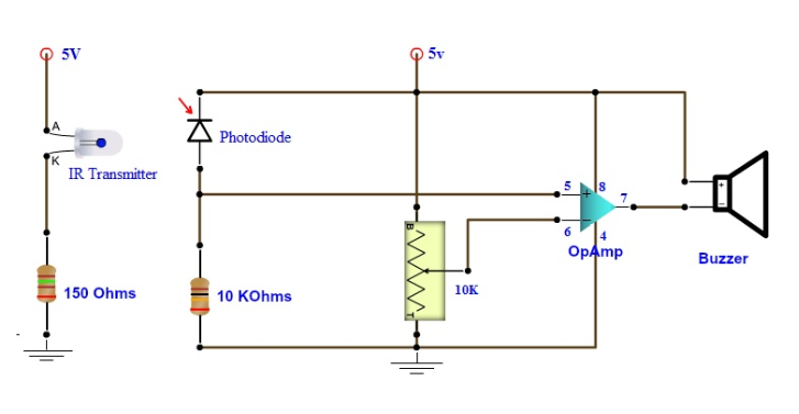
From the above figure, you can clearly see creating any effective alarm system has nothing to do with complex circuit design.
Circuit connection
Before we dig deep into the circuit connect let's learn the pin configuration of the OP AMP (LM358)
The circuit connection of the IR transmitter is fairly easy but you need to identify the anode (negative terminal) and cathode (positive terminal correctly) the larger connect part of the IR LED is known as a cathode and the shorter one is the anode. Connect the anode to a (+) 5-volt power source. Once it’s done, weld the cathode part to one end of 150 Ω resistor. After that connect the second part of the resistor to the ground and the perfect circuit is ready for your transmitter end.
Please note that you can redirect the beam of the IR transmitter by using Mirror HR RGB 10x20 available at Opt Laser for securing complex parameters. They also have items for laser engraver and different CNC laser accessories which can be used in a variety of optoelectronic projects.
Connection details of the receiving end
First of all, connect one end of the buzzer to terminal 8 and the other end to terminal 7 of the LM358. Once it’s done, use a wire to connect the terminal 8 to the (+) 5-volt terminal. Take the photodiode and connect its non-inverting end to the positive 5 bolt and the other end to pin number 5 of the LM358. Now join one end of the KΩ to 10KΩ pot and connect it to the ground. The other end of the 10 KΩ resistance should be connected to pin 5 of the op-amp and for the 10KΩ pot, connects its other end to pin number 6 of the LM358.In the last step, connect pin 4 to the ground and you have a complete burglar alarm system.
How it works
As long as light is projected in the photodiode, there will be no sound from the alarm system. But if for any reason, the light projection stops for a second, a loud sound will be triggered by the system. In case of creating a diversified path for the light source, you can use the Mirror HR RGB 10x20 to secure a large premise. But in such case, you need to use more powerful IR transmitter so that it can easily project a beam of light covering a large distance.


Comments
Please log in or sign up to comment.