


Hardware components | ||||||
| × | 1 | ||||
| × | 1 | ||||
| × | 3 | ||||
| × | 1 | ||||
| × | 2 | ||||
| × | 3 | ||||
 |
| × | 8 | |||
| × | 1 | ||||
| × | 1 | ||||
| × | 2 | ||||
| × | 1 | ||||
| × | 1 | ||||
| × | 2 | ||||
| × | 22 | ||||
| × | 1 | ||||
| × | 1 | ||||
| × | 4 | ||||
| × | 2 | ||||
| × | 1 | ||||
| × | 1 | ||||
| × | 1 | ||||
| × | 2 | ||||
| × | 1 | ||||
| × | 1 | ||||
| × | 1 | ||||
| × | 2 | ||||
| × | 1 | ||||
| × | 1 | ||||
| × | 1 | ||||
| × | 1 | ||||
| × | 36 | ||||
 |
| × | 1 | |||
Introduction
For our ECE 4760 final project, we designed and built a drum trainer that can be attached to most Japanese drum surface and will detect and wirelessly transmit different drum hit types to other players drum trainers. The trainer is able to determine whether the user makes a Loud Beat, a Soft Beat, or a âRim Shoâ, and provides feedback in the form of LEDs to tell the user what type of beat they just made. This setup allows the use of several different applications; three such applications we came up with are:
1) Follow the Leader - One drum player is designated as the leader, and as the leader plays, the timing of each drum hit get transmitted to all of the followersâ playing along with him. The followers are then notified through LEDs whether they are performing the correct hit type, and whether they are playing at the right tempo.
2) Metronome - A player can set any tempo that they would like by hitting the drum a few times at a certain speed. The trainer averages the times between hits and then provides the player with a blinking LED with a constant tempo the player can then perform at.
3) Repeat After Me - For this mode, a player first records a pattern or beat that he would like to repeat. Once they are satisfied with the pattern they created they can begin to repeat the pattern, and the trainer will tell him whether they are playing the same type of notes at the same time.
In addition, we definitely foresee other software applications that can be developed to work with our Taiko Drum Trainer. It was important to us to develop a final project that could be greatly expanded and made more useful over time if necessary.
Group picture
High level Design
Overview/Rationale
This idea was inspired by team member Gabriel Soares who is part of Cornellâs Taiko Drum Club (Yamatai). Through his practicing and performing with others, he recognized the opportunity to design a drum trainer that can help students better learn to perform their drumming when following the leader of the group and practicing with others. This device would provide them feedback of if they were performing the correct types of hits and whether they were staying at the correct tempo with everyone else.
The following video is the promotional trailer for Yamatai's annual concert that the group performs every Spring semester. For those who are not familiar with the Taiko drumming, this video does a good job at demonstrating the technique and style that the performers use. Pay close attention to the different beat types, beat intensities, and the important role that timing plays in the drummers' performance.
Overall User Interface
When designing the user interface, we needed to be able to make it easy for the user to switch between which mode/application they were using (as well as knowing which mode they were using), and we needed to be able to have them easily see whether they were beating too slowly or too quickly, and an indicator of what type of hit the trainer was detecting.
To solve these problems, we included several user friendly features. We included a simple push button to switch between applications, and included a seven segment display to display a single digit to clearly show the current mode to the user. The seven segment display key is as follows:
- 0 - Calibrate Mode
- 1 - Follow the Leader Mode
- 2 - Repeat After Me Mode
- 3 - Metronome Mode
- 4 - Free Play Mode
We also have a total of 8 different colored LEDs on the board that the user can see, grouped into a set of 5 and a set of 3. Depending on the mode the trainer is in, these LEDs serve special purposes. For most modes, the set of 5 LEDs tells the user the speed at which they are playing. If the middle LED is being lit, you are playing at the same exact speed as the other player, if the right LEDs are being lit (colored yellow) then you are playing too quickly, and if the left two LEDs are being lit (colored green), you are playing too slowly. The set of 3 LEDs usually tell you the type of hit that is being registered as you are playing the drum, with the exception of Metronome mode. The yellow LED indicates a Rim Shot, the red LED indicates a Loud Beat, and the green LED indicates a Soft Beat.
High Level Block Diagram
From a high level view of our project, our goal was to correctly determine the types of beats on each drum and transmit this data wirelessly over IR for use in various applications. We would first detect the beats on each drum using the piezo sensors. We put two piezos on each drum to better detect the difference between loud beats and rim shots. Once the beat types were detected on each drum that was active, we would use IR transceivers and receivers to send this data across the room to the other drums and be evaluated in very short, unnoticeable period of time. This project allowed drummers to communicate and play with one another, giving real time feedback on the drummerâs timing and performance.
Circuit diagrams
State machines
Prototype
Software
Our software consists of code written by Adam Harris, Adam Jelfo, Gabriel Soares and Lucas Nissenbaum. The only file this code is on is main.c, and all of our functions are located there. We do reference Bruce Landâs code for infrared communications. For this code, see this page.
The software for our drum is based on many different routines. These routines are encapsulated as follows:
Different Software Routines
Each layer works by calling the layer below it, and having access mostly to functionalities by the functions below it. The top layer defines the applications, which are the different beat modes we are using. This layer will implement the different beat and display functionality combinations. Beats will be obtained by calling the layer below, get beat. The get beat layer will get a beat and will handle any event that can happen before a beat is received. This layer also implements infrared transmission. It calls the interrupt service routine which gets each sample, and classifies the beat given the samples.
The explanation of the software project is divided in a few parts. First, we will explain the data structures used. Then, we will focus on explaining the innermost layer, the interrupt service routine. After that, we will describe the get beat function. Finally, all the applications will be explained, as well as initialization.
Data Structures
There is one main data structure used, which is a beat. A vector of beats (with BEAT_TOTAL positions) is held in memory, such that all beats are pre-allocated in this vector statically. BEAT_TOTAL has been set as 1000 beats, but may be changed easily.
typedef struct _beat_
{
long time;
long compare_time;
enum _beat_type_ type;
enum _beat_type_ compare_type
} beat;
This structure consists of the representation of one beat. It has four components. The first one, time, indicates the time the beat happened. The second variable, compare_time, indicates the reference time for the beat. The third one, type, indicates the type of the beat.The fourth variable, compare_beat, indicates the reference type for the beat. The two compare variables were used to indicate the reference beat in modes as follow the leader and repeat-after-me. Types are data instances of the enumeration indicated below, which can have a value of rim, soft or hard hits.
enum _beat_type
{
inactive,
rimshot,
softbeat,
hardbeat,
received
};
Enumerations were also used for all of our state machines. Each state corresponds as one possible value of the enumeration. Only one instance of each of the state machines was declared.
Interrupt Service Routine
ISR (TIMER1_COMPA_vect)
Our interrupt service routine is our innermost function. It was first written to implement a functionality of sampling the ADC channel every 0.5 ms. Once this was done, we enhanced it by sampling the strong filters ADC channel before a beat and the weak filters ADC channel after a beat. We also changed the sampling rate to every 0.25 ms. Note that we only sample with a precision of 8 bits, as we do not need any more precision.Once finished sampling the weak filters ADC channel, the ISR will then classify a beat, as well as save its result.
First, we need to understand how to identify a beat and how to say it is over. To do this, we use the two graphs representing beats.
The strong filtered is sampled at first. This filter has a smaller duration of time for a pulse. It aims to find the beginning of a pulse by making the pulses have smaller width. If a sample is higher than the value given by BEAT_UP_THRESH then this filter will stop being sampled, and the ISR will now sample the weak filter.
The weak filter will then be sampled to find the peak of the signal first. This value will be used in different computations afterwards. After peak signal is found, we wait until we find a signal value below BEAT_DOWN_THRESH. Once this value is found, we need N_DOWN_SAMPLES below this value to declare a signal as over. This is done such that a short duration (less than N_DOWN_SAMPLES long) drop below BEAT_DOWN_THRESH followed by a rise above BEAT_DOWN_TRESH is not treated as a new signal. Once N_DOWN_SAMPLES happen, we declare the signal as over.
To classify a beat, we check the peak of signal first. If it is smaller than BEAT_LOW_THRESH, the beat is soft, and so we classify it as a soft beat. Else, we check to see if the beat if a hard beat or a rim hit. If the length of the signal is bigger than N_RIM_THRESH, then we classify the signal as a hard beat, otherwise, it is a rimshot.
The ISR also implement reading and debouncing of the buttons. This is done by using a push button state machine as follows below. This state machine will debounce the buttons, running whenever a cycle of 8 ms is complete. This state machine is also responsible for updating variables whenever a button is pressed. We made an assumption that not more than one button would be pressed at a time, which is fair, given our usage of the buttons. Also, the ISR will implement some mode specific functionalities. These functionalities will be explained with each mode.
Get Beat Function
bool get_beat (bool ir_flag);
Get beat is a function called by the applications in order to obtain a beat or some event. In other words, get beat will wait until some event happens, and then set event (or add a beat) in this case. Get beat will expect ir_flag = TRUE as a parameter if infrared transmissions are expected. Otherwise, get beat should have ir_flag = FALSE.
This function works by first waiting for any a change in sample_state to on_beat. When this happens, it transitions to wait until the state is back to off_beat. After it changes back, the function will return TRUE. Get beat will also look for changes on its flags, such as external interrupt flag, button press flag and jump beat flag (in case of timeouts), and, if these happen, the function will return FALSE. IR transmissions will happen if ir_flag is true. The infrared LEDs will be turned on as soon as sample_state changes to on_beat, and will be turned off when back to off_beat.
7-Segment Display
Two different things are displayed on the 7-segment display. During the first second of use, the board id is displayed. To do this, we use the following function:
void display_segment_id (void);
Also, we can display the current mode on the segment display. To do this, we use:
void display_segment_mode (void);
To display something on the display, all that is done is to clear the bits of the segment port, and then shift the value that we want to display by 3 (to fit the content on the display).
Dip Switches
void read_dip_switches (void);
The dip switches work by reading the DIP_PORT (PINA), in pins A.4-A.7. This value is saved in the board_id value. This function is only called on initialize. Thus, to change the board ID, one must reset the board to read the new ID. Also, pins are inverted on our board, so we invert the bits in software to obtain the id displayed by the switches.
LED Displays
LEDâs are located on all 8 pins of port C. These displays are done using three functions.
void display_beat (int to_index);
This function will display the to_index beatâs type on the LED C.0 - C.2, where C.0 is a soft hit, C.1 is a hard hit, and C.2 is a rimshot.
void display_delay (void);
This function will display the delay between the most recent beat and its reference. This function displays in the following scale:
Table Outlining Timing Variables
void compare_and_display (void);
This function will compare the previous beat to its reference, and it will display if the types are the same (pin C.0) or different (pin C.1), as well as the delay by calling previous function display_delay.
Initialize Function
void initialize (void);
Initialize function follows a basic sequence of operations to set up all parameters relative to the other modes. First, initialize will setup timer1 to interrupt every 0.25 ms. We then setup the ADC converter to be sampled at 1MHz (for 8-bit accuracy). After that, we set up the IR 56KHz carrier generator. The code for the IR carrier was found at Bruce Landâs webpage.
After setting up the carrier, we setup the ports. Port A is set to input on all of its pins (as it has the DIP switches on pins A.4 - A.7 and ADC on A.0 - A.1). Port B is set to input on all of its pins (as it has the buttons on B.5 - B.7). Port C is set to output on all of its pins (LEDâs). Port D is set as output on all pins (Infrared transmissions D.1 and D.7 and Segment Display D.3-D.6) except for pin D.0 (Infrared receiver). Next, we set all the global state machine related variables to their initial states. Finally, we read and display the board id from the dip switches, as well as wait 1 second for the user to check the ID. We then start displaying segment mode 0, and enable interrupts.
Main Function
int main ();
The main function simply has an infinite loop which switches between each possible mode and picks the function relative to that mode. The functions for each mode are indicated below. In case of follow-the-leader, main is also responsible for differentiating between a leader and a normal player, by checking if the board_id is 0. It also calls initialize before starting the infinite loop. The main function will also check for reset flag, and, in case reset flag is on, then it will reset by calling initialize again.
Free Beat Mode
void free_beat (void);
In free-beat mode, or mode 4, the user can beat freely and look at the feedback relative to his beat type. All this function does is call get_beat until an event which is not a beat happens. This mode was quickly implemented mostly for testing calibration.
Metronome Mode
void metronome_beat (void);
The metronome mode works by first calculating the relative average of time between beats, and then blinking an LED with this average period.
At first, the function will wait for a beat, to call it first beat, while in state wait_metronome. After this first beat, it will then get as many beats as it can in order to calculate the period, by going to state average_metronome. State metronome will calculate the period once the start/stop button is pressed. In this case, it will call the following function.
unsigned long calculate_average_period (void);
This function will calculate the average time between the n beats. In other words:
Where the variation of time is defined as a function of the times of the i-th and (i-1)-th beats:
And so, using the previous definition:
Finally, after exchanging the indices of summation:
And so, we have a quick expression for the average period, which we can use as long as we have at least two samples. If we have n < 2, we will then set the period as a default of 12 bpm, or 5 seconds per beat.
Finally, once this period is calculated, the state transitions to active_metronome, where it will beat according to the given period. This is done on the ISR. If the mode is metronome and the state is active metronome, the ISR will blink its LED whenever global_time is a multiple of its time. After METRONOME_LED_DURATION, the same LED will turn off. This assumes the period is bigger than METRONOME_LED_DURATION, which, we found during tests, will always be true for a value of 200 for METRONOME_LED_DURATION (or 50 ms). If there is a beat, the type of the beat will be displayed. In this state, if there is a stop button press, then it will return to wait_metronome state, as expected.
Repeat After Me Mode
void repeat_after_me_beat (void);
Repeat-after-me mode works by comparing an original beat pattern with the repeated beats. First, we have a state set_repeat_after_me to obtain the users original beat pattern. The user thus plays a beat pattern, and then presses the start/stop button. In this case, the state transitions to wait_repeat_after_me. This state will wait for a beat. Whenever a beat is received, the state goes to repeat_repeat_after_me. In this state, the pattern will be repeated by blinking the blue LED according to the original set pattern, thus comparing the original beat to the first beat of the user.
The beat is compared to the users.
This comparison between times is done using the function compare and display. To consider misses, we treat as a miss the case when no hit is detected in the midpoint time value between one beat and the next one. Whenever a missed beat is detected all the LEDs will be turned on to signal missing a beat. After the pattern is completed, the state will return to the basic wait_repeat_after_me, as described before.
Follow the Leader Mode
The Follow-the-Leader modes functionality was to have multiple drummers playing (one drummer the leader, the others the students) where the student was trying to mimic what the leader was performing and to get immediate feedback on whether the student was playing the right beat and whether the beat was being played on time. This mode has two different functions implementing it. The first one is used only for the leader.
void follow_the_leader_leader_beat (void);
This first function is called only by the leader, and it has the same code as free beat mode, but sending IR as true.
void follow_the_leader_player_beat (void);
As can be seen in the state machine, this function will wait for a beat from either the leader (as flag external_interrupt) or from the user. In case both beat at the same time, it will remain on the initial_follow_the_leader and register both beats, as well as display time differences by calling compare_and_display. In case the leader beats first, it will go to wait_player_follow_the_leader state, where it will wait for the player to beat. In case the player times out his beat, the state machine will signal miss and transit back to the initial state. In case the player beats on time, the state will also become the initial, and compare_and_display will be called. There is also the case the leader beats before the deadline. In this case, the previous beat will be considered missed, but the state will remain the same. As for the wait_leader_follow_the_leader state, what will be done is similar. In case the leader does a beat, or there is a timeout, compare_and_display will be called (displaying miss in case of a timeout), and it will transition to the initial state. On the other hand, if the player beats, then a miss will be signaled and it will wait for a next beat from the leader.
Calibrate Mode
void calibrate ();
Calibrate mode was implemented to determine the values for voltage (beat_low_thresh) to classify a soft hit, as well as the value (n_rim_thresh). Calibration is optional, and, if the user doesn't wish to calibrate her drum, then she may use the default values of BEAT_LOW_THRESH and N_RIM_THRESH.
To calculate beat_low_thresh, we estimate the value of the peak of a weak signal by asking the user to beat two soft hits. Then, with this expected peak value, we increase it by 33% as a security margin, and declare this the threshold. To calculate n_rim_thresh, we estimate the number of samples of two rim shots, by asking the user to beat tw rim shots. Then, with this expected number of samples, we increase it by 25% as a secure margin and declare this the threshold.
Software Testing
To test our software, we followed modular practices, by adding one functionality at a time and doing thorough tests to this functionality. We did not have many bugs in our implementation, and we do not have any warnings in our code. As for the bugs we had along the way, these were quickly fixed. For example, when implementing basic get beat function, it was getting a beat every time, as we were sampling the wrong way. Also, when implementing repeat-after-me, we had a problem related to how to define this mode. We defined the reference to be the previous user beat, instead the first beat. This made the userâs beat much different than the reference beat, which was not what we aimed for. Therefore, we had to change this part of our software. Finally, when programming follow-the-leader mode, we had a problem with resetting the board, as we were filling the beat vector for infrared transmissions too quickly. This happened as we checked for positive values instead of negative edges. And so, we fixed it by checking for the transitions.
As for our accuracy, there were two main points related to obtaining a beat that should be evaluated. First, we found out that the board is precise in timing when a beat is detected. We reached the conclusion that, by tweaking parameters, we can reach accuracy higher than 90% for beat type detection for the small drums. We also have a small fraction of double beats (hard beats which are counted by the machine as two beats), though parameters can be tweaked to optimize these two fractions.
Source code
|
|
|||||
|
|
|||||
|
||||||
|
||||||
|
||||||
|
||||||
|
||||||
|
||||||
|
||||||
|
||||||
|
||||||
|
||||||
|
||||||
|
||||||
|
||||||
|
||||||
|
||||||
|
||||||
|
||||||
|
||||||
|
||||||
|
||||||
|
||||||
|
||||||
|
||||||
|
||||||
|
||||||
|
||||||
|
||||||
|
||||||
|
||||||
|
||||||
Schematics
References
Datasheets
- ATmega1284P
- Vishay VSMY1850 IR Emitter
- Vishay TSOP34156 IR Receiver
- TI 7-Segment Display Driver
- Alcoswitch 4 Position DIP Board
- LM358 Op Amp
Reference Code
Background Info
- Piezo Sensor Filter Design
- Signal Amplification Topology and Equations
- Circuit to Produce Proper Forward Voltages for IR Emitters
- ECE 4760 Final Design Requirements and Outline
- Original project page on ECE 4760
YAMATAI, Cornell's Taiko Drumming group
Hardware
Microcontroller
The principal component used in our project is the Atmel ATmega1284P microcontroller. We have become very familiar and comfortable with the ATmega1284P since this is the specific microcontroller that we have been using in labs throughout the semester. This microcontroller has countless features and functions; however, the following list outlines the more important and pertinent functions that we found useful for our project.
- 128KB In-System Programming (ISP) flash memory
- 32 input/output lines
- 32 working registers
- 16KB Static Random-Access Memory (SRAM)
- 8-channel 10-bit Analog-to-Digital converter
- 6 power saving modes selected via software
- Real-time counter, PWM, and two USARTS
Piezoelectric Sensor
Since everything begins with the piezoelectric sensor, it can be argued that this is the most important subsystem of our whole project. With this in mind, we spent the majority of the first couple weeks just focusing on the sensor. From the beginning, we knew that we would be using a piezoelectric transducer to detect a beat. This was because we were already familiar with piezoelectric sensors from previous classes and we were able to obtain them for free from the lab. A piezoelectric transducer is a device that takes advantage of the piezoelectric effect in order to measure a force or strain by converting this mechanical energy into an electrical charge. The piezoelectric effect is the phenomenon that occurs when a mechanical deformation is applied to a piezoelectric crystal and a potential difference develops due to electric dipole and surface charge density generation.
Luckily, we were able to find about twenty piezoelectric transducers in the laboratory cabinet. These piezo transducers were simply speakers that must have been used in previous labs. Unfortunately, we were not able to find much information on these piezos (SHI-1130 by Shigma) because they appear to be discontinued. However, this did not prove to be a problem because these sensors were very simple to use - they simply contain one ground lead and one signal lead. Our first test involved just holding the sensor against the drum head and connecting the leads to the oscilloscope. This test revealed that the piezo sensor produced a very large negative voltage (about -50V) and a fairly large positive voltage (+12V) followed by a sinusoidal wave that dampened over time. We would not be able to input this very large negative signal into the microcontroller for fear of damaging the input. Furthermore, if every signal gets clipped by the microcontrollerâs max input voltage, then we would be unable to decipher loud hits from soft hits.
Therefore, we searched the internet for a solution to this problem. We were able to find an extremely helpful webpage titled Piezo transducer signal conditioningâ at http://leucos.lstilde.org/wp/2009/06/piezo-transducer-signal-conditioning/. The author of this article provided helpful tips to accomplish everything we were trying to achieve: produce a positive voltage signal, restrict the bounds from 0 to Vcc, and produce a clean/predictable signal. By creating a half-wave rectifier from two Schottky diodes with forward voltage drops of 0.3V, we were able to make the whole signal positive. So we don't fry the analog-to-digital converter of the microcontroller, we included a Zener diode to cap the maximum voltage of the signal. We used a 5.6V Zener diode (found in the lab cabinet) in order to make sure that the piezo's signal voltage will never exceed the rating of the Zener diode. Finally, in order to filter the signal, we used a simple RC circuit. For our drumming application, we would like our signal to fade out in about 100 milliseconds. Since we know that the voltage will drop to 90% of the initial voltage according to the following equation, we can solve for the desired resistor and capacitor values.
Therefore, choosing R = 1M ohms, we arrive at a capacitor value of 47 nanofarads. This decision to make the signal fade out within 100 milliseconds was a difficult decision that involved a major trade-off. The circuit did not filter the signal as cleanly for small values of R and C, however we did not want to use large component values because this means the signal would not die down as quickly. After testing with multiple R and C values, we decided that a decay of 100 milliseconds produced a cleanly filtered signal, yet was still fast enough for our application. Using these resistor/capacitor values and the Schottky and Zener diodes from lab, we constructed the following circuit based on the topology of the aforementioned website article.
After testing this signal conditioning filter circuit, it became clear that we would need to build another filter if we wanted to distinguish the different types of hits. One of our original goals was to distinguish between a loud hit, a soft hit, and a rim hit. With just the one filter, we were not able to differentiate between a soft hit and a loud hit. Therefore, we decided to build another filter based on the same topology and only changed the values of the resistor and capacitor. We made this a very strong filter by producing a large decay of approximately 10 seconds. From this desired decay time, we choose a resistor value of 10M ohms and a capacitor value of 470 nanofarads. With this second filter, we also had to introduce a second piezoelectric sensor that we placed right next to the original sensor. One of the sensor is connected to the weak filter and the other sensor is connected to the strong filter. The idea is for the weak filter to distinguish between rim hits and loud hits based on the time the signal takes to decay since a rim shot will decay much more rapidly. The strong filter is used to distinguish between a soft hit and a hard hit by the voltage and does not take into account the time decay aspect of the signal. The software section (filter sampling) goes into more detail as to how our code samples and uses the data from the two filters. The following circuit is the strong filter that we used for our piezoelectric sensor.
If you'll notice in the above two schematics, the circuits each include an op-amp, which is not part of the filter. These op-amps are included to provide an amplification stage that we found necessary after our round of testing. We decided to use a simple non-inverting operational amplifier which amplifies the input signal according to the following equation:
The circuit topology and gain equations were found on the Wikipedia page for Operational Amplifiers:http://en.wikipedia.org/wiki/Operational_amplifier#Non-inverting_amplifier . Therefore, according to the above equation, the weak filter (the first filter circuit) has a gain of:
And the strong filter (the second filter circuit) has a gain of:
Infrared Emitter and Receiver
When considering the different types of methods that could be used in order to broadcast data from a leader board onto the various student boards, we decided to use infrared communication. The main reasons for using infrared as opposed to radio are: for this application the drums are always within line-of-sight of each other; distances between drums are short (between 2 to 15 meters); infrared receivers and LEDs are significantly cheaper than radio transceiver; we can broadcast data at a very fast rate (which is very important for this application since we want to be able to flash LEDs on all the boards when the leader plays the beat).
A typical practice setup is shown below, where the drums are arranged in a circle so that each player can see everyone else. We found that with the following setup, a viewing angle of 120 degrees is sufficient so that every drum can pick up the broadcasted IR data from the Leader board.
We are using two IR LEDs (VSMY1850) which have a broad viewing angle (60 degrees from each side) in order to ensure that we can broadcast beat events to the other boards without having to worry too much about the setup of the drums with regards to each other.
For this circuit we are powering the LEDs with a 9V source and connecting a 68 ohm resistor (thus driving the LEDs with roughly 80-90mA of current), and controlling the behavior of the LEDs with two output ports of the microcontroller. One port is the TX port from which we will be sending bits of data, and the other port will be used to modulate the data with 56KHz square wave. We need to modulate the data at a high frequency in order to be able to send data at long ranges and in order to filter out IR noise coming from the surroundings (such as lights, and other devices). The choice of the frequency (56KHz) is dependent on the IR receiver; the one that we are using for our project only demodulates data that is pulsed at 56KHz and filters out most other frequencies.
This circuit is relatively simple to implement and requires very little amounts of hardware. For our project we are using the TSOP34156 IR receiver which demodulates data at 56KHz and filters noise and signals at other frequencies. During our tests, we found that this receiver performed well with our IR LEDs and had very good response times.
The setup for this circuit is simple and consists of connecting pin 1 to our RX pin in the microcontroller, connecting pin 2 to ground, and connecting pin 3 to +5V through a 100ohm resistor and a 100uF capacitor. The data coming out through the RX line on a receiving board should be identical to the data being sent through the TX line on the broadcasting board.
When considering our various methods of communicating wirelessly between the boards, we decided that for this particular application, Infrared was a natural choice due to its simplicity of implementation, cost, and transmission speeds.
Beat Delay/Type Display LEDs
One of the requirements for this particular project which we identified early on was the need to have some sort of visual feedback to the drummers which would tell them how they are playing with relation to everyone else. We decided to have two separate sets of LEDs that the user can easily see.
With the setup shown the user can see the current mode he is operating in (whether in Calibrate mode, Follow-the-Leader mode, Metronome mode, Repeat-After-Me mode, or Free Play) with the 7-segment display. Depending on the mode he/she is in, the user can also get information about the type of note that they are playing and how they are playing in comparison to everyone else. The set of three LEDs tell the user the type of hit that the board detected (whether a soft, loud, or rim hit), whereas the set of five LEDs tell the user whether he/she is playing too fast or too slowly when compared to the other players. For these five LEDs,the middle blue light indicates that the user is playing on time. The LEDs immediately next to the middle one tell the user that they should either slow down or speed up by a small amount. The LEDs on the outside tell the user that they are playing too slow or too fast and that they should adjust their playing.
By using LEDs that are located within view of the userâs playing surface, we can give real-time feedback to the user so that they can focus on keeping tempo and playing on time with the rest of the group.
User Interface Hardware
Our overall user interface had to accomplish the following functional requirements:
- 1. The user interface hardware shall be inexpensive.
- 2. The user interface shall be straightforward and easy to understand.
- 3. The user interface hardware shall be small enough to fit on a drum.
- 4. The user interface shall have an apparently instantaneous response time.
In order to accomplish the aforementioned four functional requirements, we decided that the best option was to incorporate a user interface that included push buttons, a 7-segment display, and a DIP switch board. All of our projectâs features and modes can be controlled by the use of these three components. Our chosen user interface certainly accomplishes the first functional requirement because all of the components were found in the lab cabinets, and therefore, did not count againgst our budget. We believe that our user interface is very simple to use and straightforward after learning how to use it for the first time. After a quick glance at our instruction manual (see Appendices) or a lesson from a previous player, a new user will be able to quickly pick up the functionality and use our project. The third functional requirement was a little more difficult to accomplish because we are already very limited for space. By using only a 7-segment display, switch board, and push buttons, we did not add that much extra circuitry to our board. This also helped to keep the user interface simple by using less components. Finally, the fourth functional requirement was accomplished because all of these hardware components make changes that are seemingly instantaneous to the user. The following subsections go into more detail regarding the individual components of the user interface hardware.
7-Segment Display and Driver
As described above, we chose to use a 7-segment display to show the user what mode he or she is currently on. This solution is very cheap and easy to implement, plus a 7-segment display does not take up much space on a board. Fortunately, the lab cabinet was full of 7-segment displays, so we were able to borrow three of them (one for each board/drum).In order to drive the 7-segment displays, we bought three BCD to 7-segment display drivers. These drivers were CD4511B by Texas Instruments. The CD4511B is a CMOS BCD 7-segment display latch decoder driver that is used to drive common cathode LED displays. Referring to the driver's datasheet (see References section), we were able to correctly connect the driver's output pins to the pins of the 7-segment display. In between each of these connections, we placed a 330 ohm resistor in order to protect the specific LED of the 7-segment display. In addition to connecting the driver output pins, we had to bring in +5V to VDD, Lamp Test (LT), and Blanking (BL). We also had to connect ground to VSS and Latch Enable (LE). Finally, in order to drive the correct output pins of the driver, we connected the microcontroller ports D.3, D.4, D.5, and D.6 to the input driver pins A,B,C, and D respectively according to the truth table in the datasheet. The 7-segment display subsection of the Software section includes more information on the software aspect of driving the correct digits.
Board Select Parameters
While in Follow-the-Leader mode, we needed a simple way to determine which user would be the leader and which users would be the students/players. To accomplish this task, we decided to use a 4 position DIP switch. The specific DIP switch that we bought was the ALCO ADE04 which is produced by Alcoswitch and TE Connectivity. We chose to use this DIP switch because it was very cheap and small enough to fit well on our board. Additionally, this DIP switch is relatively simple to hook up and integrate into our overall circuit. As seen in the picture below, we simply hook up the output of the four switches to +5V and the input pins to ground. Once again, we use a 330 ohm resistor to connect each input pin to ground. In order to drive the input pins, we connected the microcontroller ports A.4, A.5, A.6, and A.7 to the DIP switch pins 4, 3, 2, and 1 respectively. Before powering on the boards, the users must determine that they wish to play in Follow-the-Leader mode. The leader then leaves all of his switches in the down/off position while the students put their switch board in a non-zero configuration. Therefore a user sets his/her board ID by representing the ID number in binary form through the DIP switch. Once the leader and student(s) have positioned their DIP switch boards in the desired numerical combination, all of the players may power on their boards. As soon as the board turns on, the 7-segment display will show the user's board ID for a couple of seconds. The leader's 7-segment display will show 0 while the students displays will show a number from 1-9 based on the switch combination they selected. Our program assumes that only one leader is selected if the users hope to play in Follow-the-Leader mode. This is a valid assumption to make given the application of our project as a teaching tool for newer drum players. The Software section of this report explains the code that is used to drive the DIP switches, while the following image demonstrates how we connected the switch board to the microcontroller and our board.
Navigation Buttons
The final decision we had to make regarding user interface was how the players would switch between modes and signal they were ready to start or stop playing. Our first idea was to use a keypad to select the mode, however this proved to be overkill because we only have five possible modes to choose from. Additionally, keypads are relatively expensive and very large components. Therefore, we decided to just use push buttons to cycle through each of the modes. This solution turned out to work very well because the push buttons were free (the lab cabinet had plenty of them) and they took up very little space on our board. Our final product includes three push buttons - one for the mode select, one to signal a start or stop function, and one to reset the board. When powering on the board, the default mode is always the Calibrate mode, as witnessed by the 0 on the 7-segment display. If the user wishes to switch to a different mode, then he/she simply presses the first push button. Once the user reaches the Free Play mode (number 4 on the 7-segment display) and continues to press the push button, then the modes will cycle through again starting at Calibrate mode.
The start/stop push button demonstrates its functionality in Metronome, Repeat-After-Me, and Follow-the-Leader modes. In Metronome mode, when the user wishes to begin beating the drum and set the metronome tempo, then he/she must press the start/stop button. Once the user is completed with this setup, then he/she pressed the start/stop button again to signal that the program is ready to average the beats and set the correct tempo. In Repeat-After-Me mode, the user plays the desired series of beats and then presses the start/stop button to signal that he/she is done playing. In Follow-the-Leader mode, the start/stop button allows the students board to reset itself if the student wishes to start copying the leader from scratch. All of the push buttons we are using on our boards are active low and complete the connection from +5V to ground (through a 330 ohm resistor) when the button is pushed. In order to determine the status of the push button, we have connected the Select Mode push button to port B.5 on the microcontroller, the Start/Stop push button to port B.6, and the Reset button to port B.7. The Software section of this report outlines how the code handles the push buttons mode switching, starting/stopping, and resetting. The following image shows how the three push buttons are connected to the rest of the board's circuitry.
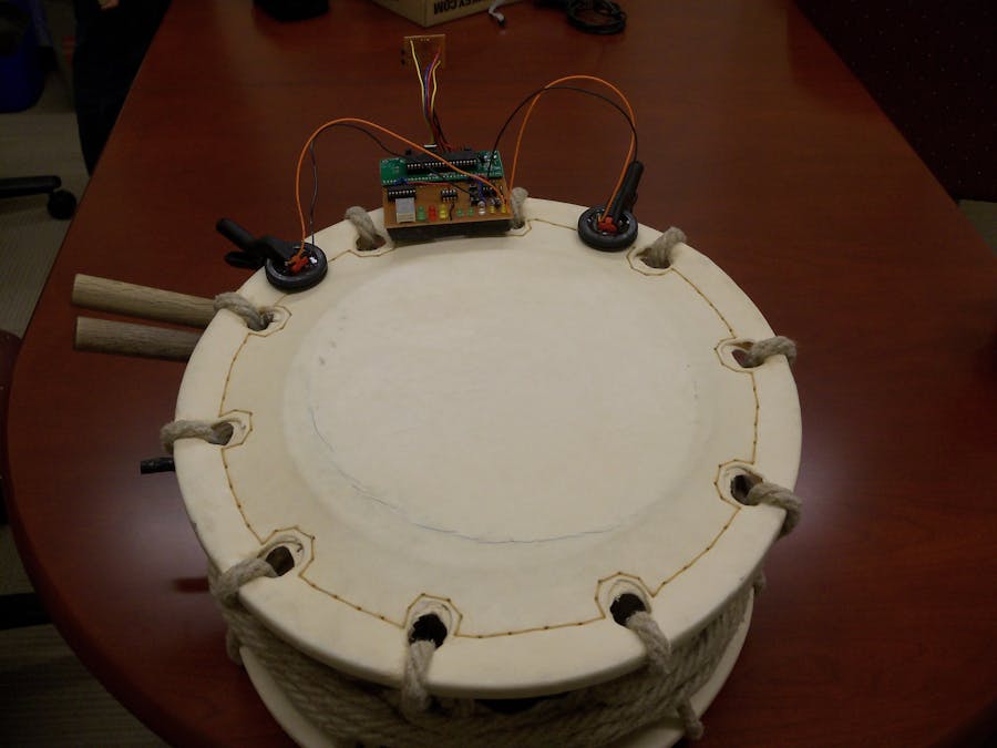
Overall Drum Integration/Setup
One of our main goals for this project was to make the final product as clean and professional looking as possible. This goal was largely dependent on how we integrated the circuitry and board onto the drum. This all started with the connection of the two piezo sensors. We decided to place the sensors on the edge of the drum head, so that they were away from the where the player beats the drum head yet still close enough to pick up vibrations. The sensors were then held in place using two clamps that were purchased at Lowes. Aesthetically, this looks a little unprofessional; however, the clamp provided the best results during our testing. We also considered using velcro to hold the sensors to the drum head, however during these tests, the sensors did not provide a suitable and reliable signal. Also, the use of clamps is very non-invasive so our product can be easily transferrable from drum to drum without making a permanent mark on the drums. We used epoxy to glue a rubber ring around the piezzo in order to protect them in the even that a student hits the sensor with the drum stick. The rubber ring also gives us a better acoustic connection with the drum head.
The sensors are connected to the main board of our project, which fits snugly onto the side of the drum head. This was a design decision that we had to make as a team because the placement of the board provides many benefits and risks. If we placed the board next to the drum, then the user would not have a clear view of the LEDs on the board because he/she would constantly have to be looking off to the side. The disadvantage of placing the board on the drum head is that there is a greater risk of the user accidentally hitting (and subsequently breaking) the board. In the end, we decided that this was a risk that we were willingly to take, given that we want the user to be able to receive the direct feedback of the LEDs without looking away from the drum. Thankfully, we were able to build a board that was small enough to be able to fit on the head of the smallest Taiko drums we tested with. This was made possible because our finished product was built onto a printed circuit board. When we began testing, it took two bread boards (and a large pile of wires) to hold our entire circuit.
Since we wanted an aesthetically pleasing final product, we decided to take the time to place the circuit onto a PCB. The schematics were created using PCBexpress and then were printed using a laser printer and then transferred onto a PCB using the toner transfer method. The schematics were ironed onto a plastic copper board which were then carefully etched out using Ferric Chloride. This etch was then tinned in lab using solder and the necessary components were added to the board. In order to keep size to a minimum, we used many surface mount components. The microcontroller board, integrated circuit chips, push buttons, 7-segment display, switch board, and LEDs were then soldered onto this board. This whole process was well worth the time and resources because we ended up with a PCB that measured approximately 3.5 x 3.75. We also designed and produced a smaller PCB (approximately 1.5 x 1.5) that housed the infrared emitters, infrared receiver, and the accompanying components for this circuitry. This little PCB is connected to the larger PCB and pointed to the other drums/boards to either transmit or receive the IR signal. Additionally, these boards are entirely powered by a 9 volt battery that is placed on the bottom of the large PCB, making our project completely self-sufficient.
Hardware Testing
Through our thorough design process of completing the Taiko Drum Trainer, we encountered several bugs and errors which we solved by rigorous testing. One of the first major problems we encountered was us not being able to accurately detect beats because at the time we were using a different type of piezo. We originally were using a flimsy type of piezo that allowed many fluctuations at the tip of it acting as how a piece of paper would in some wind. We quickly realized that this wasnât the most accurate type of piezo to get the vibrations we needed that were coming out of the drums by connecting the piezo up to the oscilloscope and not getting enough voltage response, even when we would hit the drum very loudly. This led us to find other buzzer piezos found in lab that are circular, where the whole bottom plate sits flat on the drum and fluctuates all as one. Connecting to the oscilloscope once again, we got significant voltage out of it that would be sufficient enough to do beat detection.
Another point where we had trouble in hardware was when designing the filter to limit the voltage fluctuations that would arise from the drum vibrations after a hit. We originally had one filter with a small capacitor that was simply to distinguish between the three different beat types, each of them having their own looking waveform. However, the problem arose where we needed to filter out these after vibrations to not accidentally detect a double beat and to not miss another quick drum hit after. It was important to distinguish between what was late vibrations after a hit and what was an actual new hit. To solve this issue, we ended up adding a second filter in our circuit that would connect to a second piezo on the drum. This second filter had a larger capacitor that gave us a very quick decay on the beat waveform and would thus cut out a lot of the extra voltage on the end of the drum hit. This allowed our drum trainer to be ready to detect new drum hits quickly after the previous hit, and not accidentally detect two hits out of one drum hit. We used the lab's oscilloscopes extensively during our hardware testing of the filters. The following image demonstrates a typical screenshot that we took while testing the filter circuits. In this screenshot, we performed a rim shot and then a hard hit while scoping the weak filter and strong filter.
One of the last major hardware issues we ran across was when we were actually testing the wireless transmission of pulses over infrared. We needed to make sure that we could get the range we needed out of the IR emitter because we wanted the drums to be able to be at least several feet away from each other so it would be practical in use. Since we had used simple IR emitters and phototransistors in a previous lab in the semester, we first tested with these by using a function generator to to send a square wave through the IR emitter. We connected both the emitter side, and the phototransistor side to separate oscilloscope lines to see if we could see any of the square wave through the phototransistor. Unfortunately, we found that the phototransistor wasnât getting anything, and only if we put the phototransistor and emitter directly in front of each other would we get anything small. After talking with Bruce, we found that we needed a high powered IR LED emitter and an IR receiver to get the kind of data at the range that we wanted, which he luckily had plenty supply of in the lab. So taking a pair of these high powered IR emitter and receivers, we put them into our circuit and saw great results. We were seeing the square wave come in very cleanly at a distance of several feet with no noticeable lag in time. Even when some obstructions would get in the way, or if we turned the IR emitter into a completely opposite direction, the receiver would still detect the square wave perfectly (from the light bouncing off the walls). We were obviously very pleased with this and knew this would be the way to go.
Measurements
Results
Execution Speed
One of our original goals for this project was to provide the user with apparently real-time feedback via the onboard LEDs. Throughout all of our testing we made sure that our functionality was being performed at a sufficient execution speed. From the beginning, we knew that our microcontroller was plenty powerful and fast to accomplish all of our goals, so we never used that as an excuse for poor execution speed. The board powers on very fast and all of the user interface components operate at near instantaneous speeds. For example, the push buttons changed the mode at sufficient speeds and the 7-segment display updates the mode very quickly. More importantly our LED indicators operate at apparently instantaneous speeds while the user is playing. The beat type LEDs are lit as soon as the user plays a certain beat. All of the modes have a specific set of tests that demonstrate that our execution speed is good. In calibrate mode, the LED switches once the desired beat is detected. In metronome mode, the beat type LED is displayed once the user plays a beat. In repeat-after-me mode, the LEDs are also seemingly instantaneous when they get displayed given the timing of the beat. In follow-the-leader mode, the LEDs are displayed at a proper execution time given how fast or slow the student is compared to the leader. In regards to our infrared communication, our execution speed is very good and surpasses our original expectations of using RF. This is expected because the infrared travels near the speed of light, which is definitely instantaneous to the human eye. We tested this by connecting the IR transmitter and IR receiver to the same oscilloscope and measuring the difference between the two signals. We were not able to measure a difference between the two signals either on the oscilloscope or via the LEDs on the opposite board.
Beat Type Accuracy
Detecting the correct beat type is one of the most obvious results that show either our success or shortcomings. It is obvious to the user which type of beat (hard, soft, rim) he/she just hit; therefore, the user will be able to tell whether our product works properly depending on which LED lights up. As previously mentioned, a soft hit lights the green LED, a hard hit lights the red LED, and a rim shot lights the yellow LED. We did not perform any formal or documented testing to determine our accuracy of beat type. However, we spent many hours in lab playing the drums in order to test whether the LEDs registered the correct beat type. After the addition of the calibrate function, we found that our product was registering the correct beat type a lot more often. However, we will fully admit that our board does not always register the correct beat type. If we were to guess, we would say that our beat type accuracy is around 90% to 95%. Sometimes, our device will mistake a rim shot for a hard shot and vice versa. This is most likely due to the fact that these two beat types both produce the same maximum voltage, and depend on timing aspects to differentiate these two beats. Another reason for this slight inaccuracy might have to deal with where the player strikes the drum. We ask the player to calibrate the drum by striking the center of the drum head; however, if the user strikes the drum more towards the perimeter while playing then our calibrate timing/voltage parameters may not be as optimal.
Another aspect that creates a variation in the performance has to do with the type of drum that we are using. Taiko drums vary greatly in size, shape, pitch, etc., which makes it very hard to create a one size fits all kind of product. Although our calibration feature does allow us to move our device onto different sized drums, after a certain size, the vibration on the head is so great, that the piezo pick up signals for nearly one second-long durations. For our testing purposes (and for the sanity of the TAs and other lab students) we decided to focus on small and medium sized drums.
Timing Accuracy
The timing aspect of our project is only relevant in the repeat-after-me and follow-the-leader modes. In regards to timing accuracy, these two modes are very similar because the LEDs indicate if the certain beat was either too early, too late, or just right. In repeat-after-me mode, the user first plays the desired song or series of beats and then another user (or perhaps the same original user) tries to perfectly emulate the timing of the beats. There are five possible options as shown by the range of LED: very delayed, delayed, on time, fast, and very fast. In order to test the timing accuracy we simply played the drums in this mode multiple times. We did not perform any formal testings or measurement, since we did not feel that this was necessary. Our rationale for testing was that if the results were sufficient enough for us while we were playing, then the user will be pleasantly satisfied with the product as well. While in the repeat-after-me mode, the green LEDs are displayed instantly after the player hits the drum (assuming that he/she hits too early). If the user beats too late, then the yellow lights will turn on seemingly instantaneously. And if the player completely misses a beat, then all of the LEDs will turn on after a little cushion time that we set in software. While in follow-the-leader mode, our timing results are also sufficiently acceptable for our application. The results for this mode were very similar to the results we found in repeat-after-me mode. When playing in this mode, the students also receive apparently real-time feedback via the LEDs. When the player strikes the drum (either too early, too late, or right on time), the LEDs will blink instantly to the human eye.
Safety
When we were brainstorming final project ideas, it was important to all of us that our project was very safe for the end user. We are pleased that our final product did turn out to be a safe teaching tool. The only foreseen safety issues that our project may possess deal with safety issues that are already evident during drum playing. For example, a user of our product may accidently hit himself (or a bystander) with the drum stick. Additionally, hearing damage may occur for users of our product if the user plays very loudly over a long period of time. Of course, these two potential safety issues are not caused by our device, so we consider our product to be very safe.
User Friendliness
One of our original goals for this project was to make a final product that was as close to commercial-ready as possible. We did not want to demo a product that was just a pile of wires on the table as Bruce Land likes to say. A benefit of making a professional looking product was that the overall user friendliness of the product would be first-rate. For example, a user would much rather use a product that was clean and concise than a product that was messy and convoluted. We are fairly pleased with the user friendliness and aesthetics of our final product. The printed circuit boards came out very well and turned out to be a great decision for our final product and well worth the many hours that Gabriel put in designing, printing, and soldering them. The PCB is significantly cleaner and smaller than the original protoboards that we started building and testing on. This cleanliness contributes to the overall user friendliness because it is definitely more aesthetically pleasing. We wish we could have spent more time making the piezoelectric sensor connects more user friendly and professional looking. We ended up attaching the sensors to the drum heads by using a bulky clamp and then connecting the piezoelectric leads to the board via soldered wires. This setup looks a little unprofessional, but it works perfectly fine for our application so we did not spend more time brainstorming better ways. We also reached out goal of making the use of our device very user friendly. We believe that the 7-segment display, push buttons, and switch board provide a very simple and straightforward way for the user to interact with our product. A new user can quickly pick up on how to use our product either by reading the instruction manual or asking for help from a previous user. The LEDs are always a simple and effective tool for real-time user feedback that we are very pleased with.
Conclusions
Results vs. Expectations
When first starting out in the early stages of this project, we had many thoughts and expectations that didn't exactly turn into reality in the final product. We first imagined that we would be able to detect not only loud beats, soft beats, and rim shots, but also whether they would be hit on the right or left sides of the drums with their respective hands. This goal was set because Taiko drummers do need to play specific beats with either their right or left hands. However, we found that it was difficult enough to be able to correctly determine the different types of hits in addition to whether they were on the left or right side of the drum. We would have had to use many more piezo sensors, making sure they were all evenly spaced and identical on each drum, and it would have been too cumbersome to drum on with all of the sensors being there, so the idea was quickly dropped.
Our original idea for being able to wirelessly transmit our beat detection was to use RF emitters and receivers, for we were sure it would provide speedy sending and receiving rates, as well as being reliable in the distance of transmission. It turned out that the RF transmitters and receivers we would use to operate at a legal frequency were a little too expensive to use under our $100 budget. But thanks to the assistance of Bruce Land and the TAs, we were given high powered IR transmitters and receivers that had very good range and response times.
Overall, though not as cleanly as we originally thought, we were able to successfully determine the different beat types being played by the drummer. This was the most essential part of the project, for which the rest of the software applications would've been futile.
Future Considerations (Room for Improvement)
If we were ever to develop this project further and make it more into a consumer product, there are several things we would consider adding to make it more user friendly. Though we did a good job of making small boards and attaching them to the drum via velcro, we are using rather big clamps to hold the piezo sensors to the drum head that are a little distracting and can maybe get in the way. We explored other options like glue, velcro, tape, etc. but they would all restrict the proper vibrations needed out of the piezo for us to correctly determine beats. If we had much more time to build a more stable product for consumers, this is definitely something we would look at. As mentioned earlier, another area where we could have improved was to identify hits on the right and left sides of the drums, which wouldâve been possible with more testing, time, and resources. Other than these points, our product is fairly acceptable in terms of being used by consumers, with hardly any wiring due to our soldering efforts.
Given more time, we could have also provided more feedback to the users rather than just the onboard LEDs. For example, we contemplated saving the data (beat type and timing accuracy) and then sending the data to a MATLAB script that plotted the beat types and timing differences between the leader and students. While we definitely appreciate the value added of this type of graphical feedback, our original requirements did not include this specific functionality. We also like that the LEDs provide real-time feedback and do not require the users to connect to a computer and make the system more complicated than it has to be.
Relevant Standards
Our project follows all legal and relevant standards of the industry. Our project is powered by a simple 9V battery and emits data through infrared in an allowable frequency range. This was one of the main benefits of using infrared communication instead of radio frequency communication - we did not have to comply with the allowable frequency ranges set by the FCC.
IP: Patents, Trademarks, and Copyrights
Our project incorporates many different functions and ideas that can potentially be found in other products that are already to market. The metronome function for example is a very common tool for musicians that is usually set either by analog or digital means to a specific bps. Our project puts a unique spin on the metronome idea by the person actually beating the drum and setting the metronome speed that way. For the repeat after me mode, this is also a common game that is in many products like Simon Says. But most of these repeat after me games are all done by repeating a computer program. The way our repeat after me mode works is by repeating another player and our trainer giving the player feedback on how well he/she is performing. As for the follow the leader mode, this is an idea we don't think we have seen before. The concept of a teacher playing with a group of students, and the students being able to effectively see on their own drums how they are performing in comparison to their teacher in real time we think is pretty unique. The idea and design of our project is completely owned by Adam Harris, Adam Jelfo, Gabriel Soares, and Lucas Nissenbaum.
Ethical Considerations
While designing and building our project, we constantly strove to abide by the IEEE Code of Ethics. We believe that we properly and sufficiently abided by all of the codes laid out by the IEEE. Specifically, we made all of our project decision with the welfare and safety of the user in mind. We do not believe that our product poses any danger besides the slight inherent danger that comes from playing drums. We also reported all of our results accurately and clearly outlined our shortcomings and areas for improvement in this report. While brainstorming this idea, we did our best to make sure that our project idea was original and did not unfairly copy any commercial product or existing project. In terms of ethical considerations that relate to our ECE 4760 class, we believe that we selected a project that properly challenged us and provided us with an enjoyable final five weeks. Since this is a microcontroller design course, we feel that our project sufficiently takes advantage of the microcontroller's capabilities and the lessons we learned throughout the semester.


Comments
Please log in or sign up to comment.