The Task
For the last stage of the remote control building process, we were tasked with evolving the chassis from our last iteration.
With little time, and lots of help from Chris, I pursued this design, shown in the sketch below and my final Illustrator file.
I wanted to create a slanted chassis with the weight of the vehicle dominantly in the front, for more traction when ascending ramps. This would put more weight on the weights, versus the marble at the back of the vehicle. The cut outs on the back of the vehicle cut the weight, but also served their purpose aesthetically.
I tested my first iteration with cardboard, and tried out many different hole placements for where my Arduino and H-bridge would be fastened to the vehicle. The two holes on the left of the picture are for fastening the 3D printed marble holder I attached to the back.
I tried folding the car at a 20 degree angle, for a subtle slant, and found that i would need to bend the final vehicle at the marble-roller base end as well.
My next iteration, with suggestions from Chris to be more Tron-like, was largely similar in structure, but I changed the fastening holes to slots, in horizontal and vertical directions to allow for the most flexibility in fastening, in addition to looking cleaner than a bunch of holes. The tail end of the vehicle was also slimmer, so I rotated the fastening holes for the marble holder to fit.
Here's how the Arduino, H-bridge, and motors all fit onto the cardboard prototype. As a result, I widened the chassis, and rotated the orientation of the Arduino and H-bridge, for a cleaner cable layout in the next iteration.
In the next iteration, I used acrylic, and used an acrylic bender, which heats the plastic, to reshape the design, shown below.
Here's how it turned out
I tried the prototype again (in green below), this time with a steeper incline, to test its balance, aesthetics, and traction on the ramp. On all fronts, the more subtle incline was more successful.
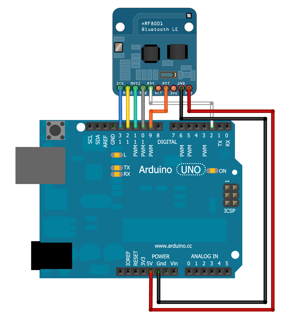
Next, I used risers, screws, and nylon nuts to fasten the H-bridge (right) and Arduino (left), to the vehicle. Prior to this, I transferred the connections of the Bluetooth receiver and Arduino to an Arduino proto shield, which worked great. Later, I replace the jumper wires with shorter leads.
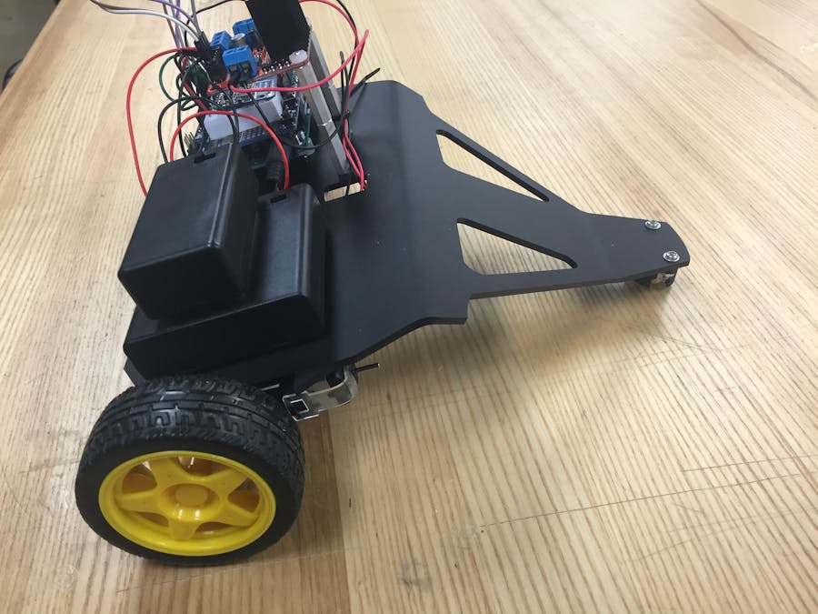
Here's how it turned out with the gear motors attached by double sided mounting tape, and the marble holder fastened to the back. I also added holes for the gear motors' wires to reach the Arduino more directly and ziptied wires for a cleaner look.
Here's how it drove:
https://youtu.be/CbkL2NOb30c


Comments