


Hardware components | ||||||
 |
| × | 1 | |||
| × | 1 | ||||
 |
| × | 4 | |||
 |
| × | 1 | |||
 |
| × | 14 | |||
| × | 1 | ||||
 |
| × | 1 | |||
Software apps and online services | ||||||
 |
| |||||
Due to the big windows of my room, sunlight gets trapped inside my room very easily which creates a lot of heat, especially during the summer (the greenhouse effect). My idea was to automate my ceiling fan in my room. Using a temperature sensor and servos, I would create a device that feels the temperature of my room and use a combination of if-statements to make the servos turn on my fan when it gets hot and turn it off when it gets cold, to get my desired temperature.
For this project I would need:- 2 servos
- A temperature sensor
- Basics (particle photon 2, breadboard, jumper wires, etc…)
1.
First I attempted using...
SHILLEHTEK DHT22 Digital Temperature and Humidity Sensor Module with Cable - Temperature Humidity Measurement for Arduino, Raspberry Pi, ESP32 and other Microcontrollers, Electronic Practice DIY
but unfortunately it was not compatible with the Particle Photon 2 so I had to use...
uxcell NTC Thermistors Resistor MF52-103/3435 10K Ohm Inrush Current Limiter Temperature Sensor Pack of 60
2.
WWZMDiB SG90 Micro Servo Motor for Arduino Raspberry Pi DIY (3 Pcs)
(I used 2)
Steps Breakdown:Part 1:
- Figure out how the Thermistor Resistor was going to feel the temperature of my room and return actual temperature values (programming)
- Test the temperature-sensing portion
------------------------------------------------------------------------------------------------------------------------
Part 2:
- Figure out how to use the data from the Thermistor Resistor to turn on the servos (programming, alternating between servos, etc…)
- Wiring the servos
- Testing together
Thermistor Resistor:
- The Thermistor Resistor uses an analog input to return voltage data that relates to the relative value of temperature in the room, it does not return temperature values on its own.
- The Thermistor Resistor first returns different voltages by changing its resistance to represent the relative temperature in a room.
- Creates more resistance = More heat.
- Creates less resistance = Less heat.
- The 10k ohms Thermistor Resistor I used needs a 10k ohms resistor. Analog input essentially takes the difference between the voltage in the Thermistor Resistor and the resistor. Since the Thermistor Resistor's resistance is constantly changing, different voltage values are returned after finding the difference.
After returning the voltage, it requires an equation to convert the returned voltage values to accurate temperature values modeled by:
I started trying to manually make the conversion through research until I came across a public library that would simplify the Thermistor Resistor process for me.
Library:
- This library was supposed to convert voltage values returned by the Thermistor to temperature but was inefficient to print accurate temperature values which I tested by using a serial monitor https://serial.huhn.me/ (was returning values all the way under -150 degrees in Fahrenheit)
Eventually, with help, I came across https://www.circuitbasics.com/arduino-thermistor-temperature-sensor-tutorial/ granting me a perfect substitution for the library, allowing me to print accurate values on the serial monitor.
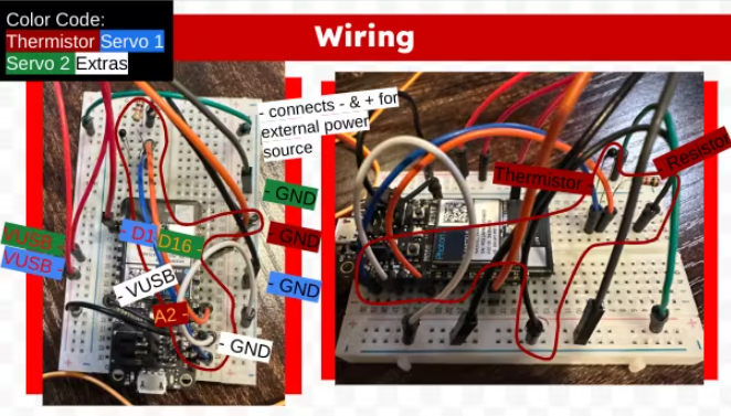
Wiring (Thermistor resistor only):
Tests:
Video 1:
https://drive.google.com/file/d/1D1KhEfjsloXzVamthAy4DXguwOM53H7R/view?usp=sharing
- The Thermistor is tested through the Serial Monitor to see if it returns accurate temperature values. In the video it displays around 73 degrees Fahrenheit on Serial Monitor which my thermostat confirms.
Video 2:
https://drive.google.com/file/d/1coxrjQtC0buxC9BTwbB_4ocPxIjMBjNg/view?usp=sharing
- I pressed against the Thermistor Resistor with my fingers to apply body heat, mimicking a hot room. When I let go, over time the temperature would decrease again to readjust to the room. This tests to see changes in temperature, evaluating if it continues returning accurate values that I can use when I start using my servos.
Now that the temperature-sensing portion is complete, we can move on to the set up of the servos and transferring Thermistor-returned temperature data to activate them...
Process (Part 2):Code:
- I used 2 servos. I was required to use 1 for the top of my fan's switch (to turn it on; "onSwitch") and one for the bottom of my fan's switch (to turn it off; "offSwitch")
- I also had to set the degrees of the positions that servos would move to when they are on and when they are off
- The actual code was relatively straight forward knowing that I would have to simply make if statements; "if the temperature is above ____, turn onSwitch on, if the temperature is below ____, turn offSwitch on."
- The problem here is that I have to simultaneously use two servos which means that in order to turn one on, I have to turn the other off. This required me to make booleans to represent the status of the switch as a whole; so I made the booleans switchOff (initialized to true since my fan starts off) and switchOn (initialized to false since my fan is not on).
- This therefore acknowledges when one is on already and off already, ensuring my code won't be prompted to turn on a servo that is already on or vice versa.
- Another aspect I created in my if statements was a for loop that incremented through every degree from the starting position that I set my servos to, to the end position at 15 milliseconds a degree, which meant that my servos weren't going to immediately change position but move there steadily.
- So essentially, the if-statements set a threshold of temperature for the servos to activate, and if it makes the threshold, it will then proceed to check if the switch is already on or off and then activate the servo to push against the switch and afterward return to its original position. The booleans update after the process as well, to update the status of the switch.
A problem I later encountered was that my looping code originally was organized like this:
- check temperature sensor for returned temp
- delay
- if temp > ___, turn on fan
- if temp < ___, turn off fan
- delay
My delays were messing up my code and servo execution because delays are meant to halt the entire code before moving on to the next line of code which therefore resulted in problems since I needed to continue the processes of checking temperature and moving servos at the same time.
My solution was to implement the millis(); function.
- millis() returns the number of milliseconds since the program started running.
This code is essentially constantly checking the temperature through intervals by updating the last time it was checked in my loop while allowing everything else to still run.
Power Source:
Wiring servos requires one pin on a digital input (must support pulse-width modulation (PWM)), one from ground (GND), and one from VUSB.
- A problem with using two servos is it will NOT work properly when the power source is a Chromebook because it is not enough to power 2 working servos.
- Therefore I implemented a 5V outlet cable to be able to power both servos
- I simply added 2 wires for the + and - of the outlet cable and attached both wires to the breadboard to take everything on the matching + and - sides of the breadboard.
Now it was time to put everything into place using extra materials to attach everything:
- command strips
- duct tape
The switch on the very left turns my fan on and off so that is where I planned to put my servos
1.- As shown on the bottom left side of the breadboard, the black and red wires extending outward are the wires that connect to the outlet cable. The wires are supposed to connect to everything on the - and + sides of the breadboard.
(I had my mom film for me for a better angle of the fan)
Video:
https://drive.google.com/file/d/1YKA_EV0zu6_5DrDQWdTwOBq85VqVVjm8/view?t=18
I use a blow-dryer to apply an increase of heat for the Thermistor resistor to feel; prompting to turn on my fan. Afterward, I turn off the blow-dryer to readjust to normal temperature for the Thermistor to feel; prompting to turn the fan back off.
Total project


Comments